2021 DOCUMENTACIÓN TECNICA - TECHNICAL DOCUMENTATION
←
→
Transcripción del contenido de la página
Si su navegador no muestra la página correctamente, lea el contenido de la página a continuación

2021   DOCUMENTACIÓN TECNICA
       TECHNICAL DOCUMENTATION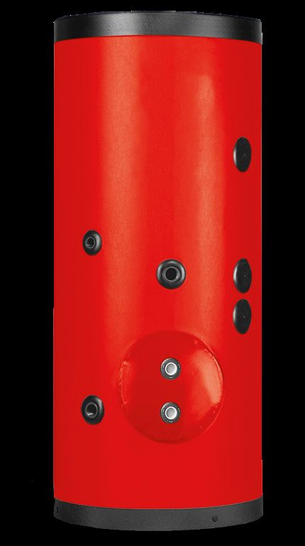
GUÍA DE SIMBOLOS PLANTS AND PATENT
Instalaciones con generadores tradicionales             Instalaciones con generadores de bomba de calor
Plants with generators at traditional                   Plants with generators at heating pump

Instalaciones con generadores de biomasa                Instalaciones con generadores a vapor
Plants with generators at biomass                       Plants with steam generators

Instalaciones con generadores de condensación           Instalaciones para diferentes fuentes de energía
Plants with generators at condensation                  Plants for different energetic sources

Instalaciones para la explotación de la energía solar
Plants for the exploitation of solar energy
Los interacumuladores, acumuladores, autoclaves y depósitos se dividen según sus diferentes aplicaciones
y uso para los que están destinados. Para cada producto es posible identificar todas las características téc-
nicas y de construcción principales, los diferentes tipos de acabado y el rango de capacidades. Un símbolo
y un color indican el sector de destino del producto que proporciona cinco sectores de producción / uso di-
ferente: características técnicas y de construcción principales, los diferentes tipos de acabado y el rango de
capacidades. Un símbolo y un color indican el sector de destino del producto que proporciona cinco secto-
res de aplicación / uso diferente:
Storage cylinders, storage tanks, autoclaves and tanks are subdivided in relation to the area of application
and the intended use. Each product is complete with all the main technical and constructional specifications,
the different types of finish and range of capacities. Symbol and colours are used to identify one of five dif-
ferent areas of application of the product:

               A.C.S. Heating
               Interacumuladores, murales , serpentín fijo, con intercambiador extraíble.
               Acumuladores de agua caliente sanitaria, calderas de vapor y recipientes de expansión.
               Storage cylinders with coils, removable heat exchangers, tank-in-tank,
               hot water storage tanks and expansion vessels.

               Energías alternativas Alternative energy
               Interacumuladores, cilíndricos solares con intercambiador extraíble y fijo para bomba de
               calor. Sistemas combinados para instalaciones sanitarias, de calefacción y puffers.
               Solar storage cylinders with removable and fixed heat exchangers,
               combined systems for domestic hot water and central heating systems.

               Inercia Inertial

               Acumulador para agua técnica, Instalaciones de calefacción y frío.
               Storage tank for technical water in heating and cooling stystem.

                                                                                                                  1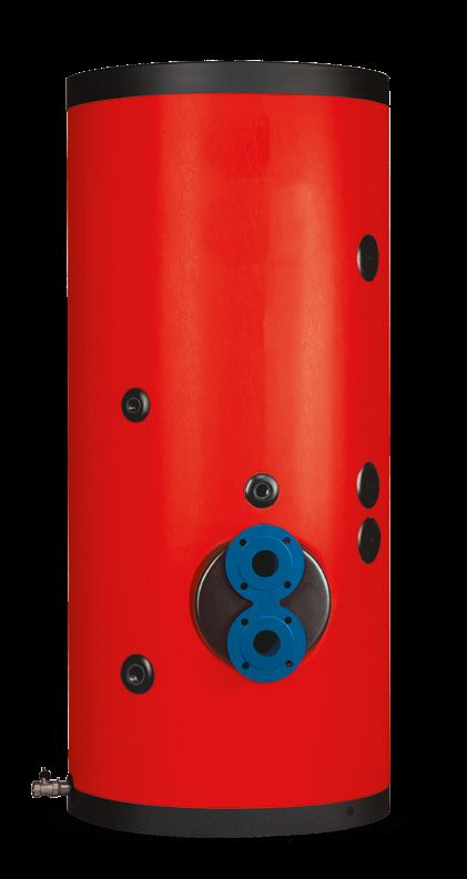
Indice catalogo tecnico
                NSIX-NSIXE
    Technical catalogue contents

      EVP				                                                                                                      pag.   12
      Interacumulador con intercambiador extraíble Storage tank with removable heat exchanger

      EVP LOW				                                                                                                  pag.   15
      Interacumulador con intercambiador de calor VERSIÓN ALTURA REBAJADA Storage tank with removable heat
      exchanger LOWERED VERSION

      116				                                                                                                      pag.   18
      Acumuladores de agua caliente sanitaria Domestic hot water storage tanks

      116 LOW				                                                                                                  pag.   20
      Acumuladores de agua caliente sanitaria ALTURA REBAJADA Domestic hot water storage tanks LOWERED VERSION

      EOP				                                                                                                      pag.   22
      Interacumulador horizontal con intercambiador extraíble Horizontal storage tank with removable heat exchanger

      VAP				                                                                                                      pag.   25
      Interacumulador con intercambiador de calor extraíble para vapor Storage tank with removable heat exchanger
      for steam

      SPTEX				                                                                                                    pag.   27
      Interacumulador mural con serpentín espiroidal fijo Storage tank with fixed spiral coil

      Repuestos y accesorios Termo                Spare Parts and accessories Heating                              pag.   29

      NS1				                                                                                                      pag.   31
      Interacumulador solar con UN intercambiador de calor extraíble Solar storage tank with ONE removable heat
      exchanger

      NS2				                                                                                                      pag.   34
      Interacumulador solar con DOS intercambiadores extraíbles Solar storage tank with TWO removable heat exchan-
      gers

      NS3				                                                                                                      pag.   37
      Interacumulador solar con TRES intercambiadores extraíbles Solar storage tank with THREE removable heat
      exchangers

      SECX				                                                                                                     pag.   40
      Interacumulador con serpentín cónico fijo ALTO RENDIMIENTO Storage tank with HIGH PERFORMANCE fixed coni-
      cal coil

      CAL				                                                                                                      pag.   42
      Interacumulador solar con serpentín espiroidal fijo Solar storage tank with fixed spiral coil

      CMAX				                                                                                                     pag.   44
      Interacumulador con serpentín espiroidal fijo Storage tank with fixed spiral coil

      SOL				                                                                                                      pag.   46
      Interacumulador con serpentín espiroidal fijo Solar storage tank with double fixed spiral coil

      SOL PDC			                                                                                                   pag.   48
      Interacumulador con doble serpentín espiroidal fijo Solar storage tank with double fixed spiral coil

      EVO                  			                                                                                     pag.   50
      Interacumulador solar con doble serpentín espiroidal fijo Solar storage tank with double fixed spiral coil

      MT				                                                                                                       pag.   55
      Interacumulador estatificado con intercambiador de calor integrado para solar y A.C.S. instantánea
      Buffer tank with solar fixed spiral coil and corrugated fixed coil
2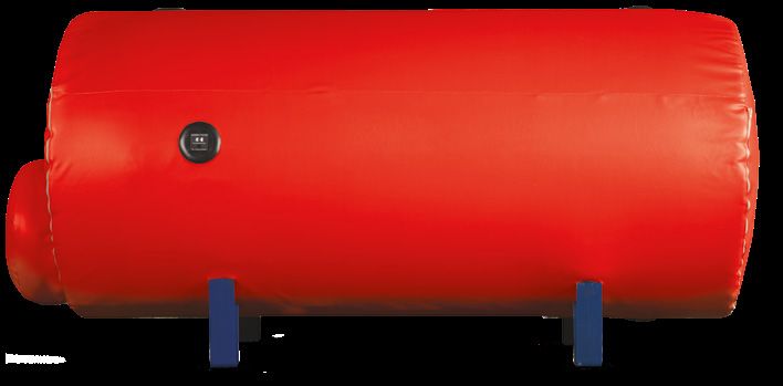
Ejemplos de plantas Example of a systemE                                                      pag.   6o

EVO 1 BASIC		                                                                                 pag.   62
Acumulador térmico para calefacción y agua sanitaria instantánea
Buffer tanks for heating systems and domestic

EVO 2 BASIC		                                                                                 pag.   64
Acumulador térmico para calefacción, termosolar y agua sanitaria instantánea
Buffer tank for heating, thermal solar and domestic

EVO 3 BASIC			                                                                                pag.   66
Acumulador térmico multienergético, solar térmico y sanitario
Solar buffer tanks for heating systems, thermal solar and domestic

PS6X			                                                                                       pag.   68
Puffers para sistemas de calefacción Buffer tanks for central heating systems

PB			                                                                                         pag.   70
Puffers para sistemas de calefacción Buffer tanks for central heating systems

PB1R			                                                                                       pag.   72
Puffers solares para sistemas de calefacción Solar buffer tanks for central heating systems

PB2R			                                                                                       pag.   74
Puffers solares para sistemas de calefacción Solar buffer tanks for central heating systems

218				                                                                                       pag.   76
Depósitos de inercia para sistemas de refrigeración Storage tanks for cooling systems

218GHC				                                                                                    pag.   79
Depósitos de inercia para sistemas de frío y calor con aislamiento aumentado
Storage tanks for cooling and heating systems thicker insulation

                                                                                                     3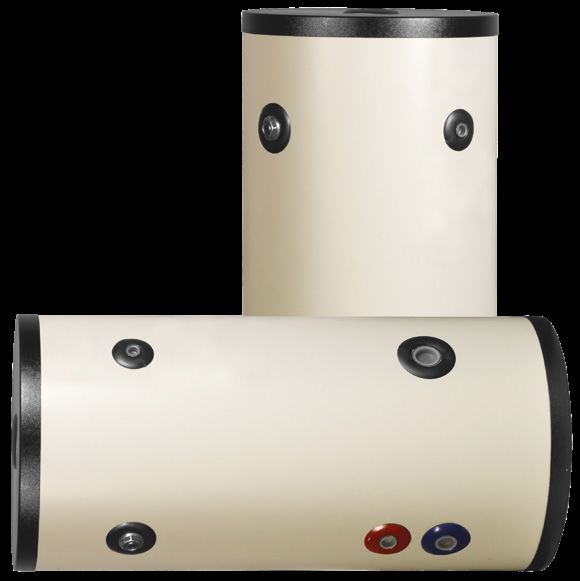
Fabricamos depósitos que mantienen el valor de sus características a lo largo del tiempo
To make tanks whose features keep their value over time
Con esta simple guía, nos ocupamos diariamente del diseño, compra de materiales, fabricación y prueba de depósitos para aplicacio-
nes termohidráulicas, para aire comprimido y para el sector.
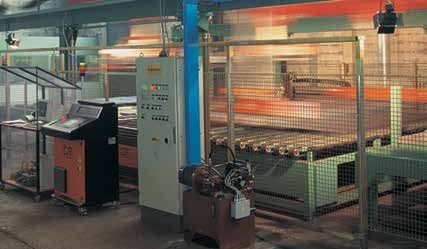
En nuestra fábrica de 55,000 metros cuadrados fabricamos depósitos estándar pero también diseñados y construidos de acuerdo con
las necesidades técnicas específicas del cliente. Todos nuestros productos están hechos íntegramente en Italia, en Rovigo.
Gracias a nuestras certificaciones de procesos y productos, suministramos a las principales empresas de ingeniería y plantas nacio-
nales y extranjeras, mientras que con la logística y la amplia red de agencias representativas estamos presentes diariamente en la
distribución especializada.
En el mercado global actual, las empresas tienen una posición influyente en la configuración de la forma en que funciona el mundo y el
futuro. Por esta razón, las organizaciones deben reconsiderar el impacto social y ético de sus actividades y políticas. Las empresas que
pueden demostrar un compromiso con la Responsabilidad Social ciertamente tienen una ventaja competitiva, inspirando la confianza
de sus clientes, inversores, consumidores y comunidades locales.
Esto está guiando nuestras actividades, comprometiéndonos diariamente a respetar las normas de calidad más estrictas impuestas por
las regulaciones pero también generadas por nuestro sentido cívico.
This simple rule guides us, every day, in designing, purchasing materials, constructing and testing tanks for applications in the heating,
compressed air and oil & gas sectors. In our 55,000 sq. m factory we have been making both standard tanks and models designed and
built to our customers’ specific technical requirements. All our receivers are entirely designed and produced in Rovigo, Italy.
Process and product certification means we supply the leading national and foreign systems and engineering companies, while our
logistics and extensive network of agents and representatives ensure our products are always available through specialist distributors.
In today’s global market, businesses have considerable influence in shaping how the world and the future will be. This is why organisations
need to reconsider the social and ethical impact of their operations and their policies. Companies that demonstrate commitment to so-
cial responsibility certainly have a competitive advantage, inspiring loyalty in customers, investors, consumers and the local community.
These are the aspects that guide our business, committed every day to ensuing the strictest quality requirements set by standards and
dictated by our sense of civic responsibility.
5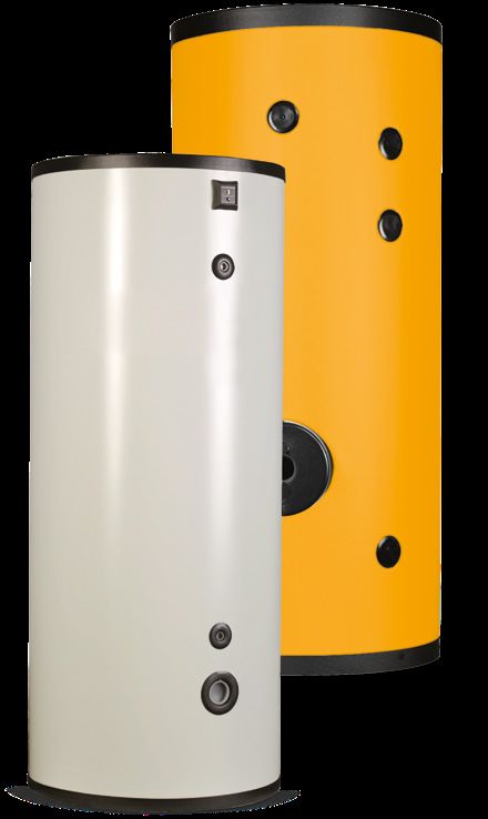
Calidad y medio ambiente: una elección ecológica
                 NSIX-NSIXE
    Quality & the environment: an ecological choice

     POLÍTICA DE CALIDAD - UNI EN ISO 9001: 2015
     El objetivo principal de la política de calidad es la satisfacción del cliente y la mejora continua de la calidad y fiabilidad del producto
     en un contexto de rentabilidad adecuada.
     Nuestra empresa tiene la intención de perseguir los objetivos de calidad y su mejora. Por esta razón, se debe buscar la calidad en
     cada etapa y momento de la actividad. Se debe tener especial cuidado en la aplicación de métodos de calidad, en el diseño, en la
     implementación de las tecnologías de productos de la compañía, en las pruebas y en la entrega y asistencia al cliente de los productos
     terminados. La entrega debe ir acompañada de manuales de usuario y de instalación, así como todos los demás documentos técnicos
     necesarios.
     Nuestra empresa tiene la intención de alcanzar la calidad a través de la difusión en todos los empleados de los siguientes principios
     básicos:
     • trabajo sin errores (ejecución correcta del trabajo desde el principio);
     • satisfacción del cliente;
     • gestión de prevención en las actividades corporativas generales;
     • cumplimiento de las leyes obligatorias.
     El logro de lo anterior se convierte en el punto de partida para la mejora continua que debe involucrar a todo tipo de trabajo en cual-
     quier situación operativa.
     Para obtener estos resultados, en particular, es esencial:
     • conciencia constante de las necesidades del cliente, expresas o implícitas;
     • un proceso ininterrumpido de capacitación y educación del personal;
     • conciencia adecuada, participación y empoderamiento de personas individuales a través de momentos de
      reunirse y compartir, para establecer una visión global que favorezca acciones organizacionales efectivas;
     • una actitud personal en todos los niveles orientada concretamente hacia el cumplimiento de las expectativas del cliente;
     • una mejora continua de los sistemas de planificación y control de los aspectos productivos y financieros de la empresa;
     • logro y mantenimiento de la Certificación según UNI EN ISO 9001: 2015.
     Por lo tanto, cada persona debe sentirse responsable de la calidad de su trabajo y cada acción y actitud debe considerarse y evaluarse
     sobre la base de esta responsabilidad.
     Se brinda amplia información y difusión dentro de la empresa de la política de calidad expresada por la Administración.

     QUALITY POLICY - UNI EN ISO 9001:2015
     The main objectives of our quality policy are customer satisfaction and continual improvement in product quality and reliability, within
     a context of appropriate profitability. Our company is committed to pursuing these quality and improvement objectives. For this reason,
     quality is pursued in every step and every stage of our business. Special care is paid to applying quality methods in design and develop-
     ment of company product technology, testing, delivery and service to the users of the finished products. Products are delivered with user
     and installation manuals and all other necessary technical documents.
     Our company aims to achieve quality by instilling awareness of the following essential principles in all employees:
     •    error free work (all operations completed right first time);
     •    customer satisfaction;
     •    management of prevention within the company’s operations;
     •    compliance with applicable laws.
     Achieving these aims is the starting point for continual improvement, which must involve all work done in every operational situation.
     Indeed, the following are fundamental in achieving these results:
     •    ongoing staff training and education;
     •    constant awareness of customer needs, both explicit and implicit;
     •    awareness, involvement and assumption of responsibility by individuals through meetings and exchanges, so as to establish a global
          vision that encourages effective organisational actions;
     •    personal attitude at all levels focused on satisfying customer expectations;
     •    continual improvement in the company’s production and financial planning and control systems;
     •    achievement and maintenance of certification according to UNI EN ISO 9001:2015.
     Each person must therefore be responsible for the quality of their own work, and each action and attitude must be considered and as-
     sessed according to such responsibilities. Considerable information is provided throughout the company on the quality policy expressed
     by Management.

6
POLÍTICA MEDIOAMBIENTAL - UNI EN ISO 14001: 2015
La empresa reconoce como una prioridad operar para que sus actividades y servicios causen el menor daño al medio ambiente,
adoptando los principios de protección ambiental y buscando la mejora continua de su sistema de gestión ambiental. Por esta razón,
la Gerencia expresa su compromiso de promover la correcta gestión de todas las actividades directamente realizadas o controladas,
prestando especial atención a aquellas que tienen un mayor impacto ambiental.
Los lineas estratégicas que forman la base para las decisiones operativas tomadas son:
• cumplimiento de toda la legislación nacional, regional y provincial sobre protección del medio ambiente, así como todas las dispo-
siciones firmadas por la empresa;
• prevención de la contaminación mediante la adopción de actividades de monitoreo y control;
• la mejora continua de su desempeño ambiental a través de la planificación de objetivos y metas ambientales específicos; este com-
promiso debe ser generalizado en todos los niveles de la organización;
• capacitación de todo el personal que trabaja dentro de la estructura en temas de protección y mejora del medio ambiente y
sobre el efecto que su actividad puede tener en el medio ambiente;
• la adopción de técnicas y productos alternativos para ser utilizados en procesos con mayor riesgo ambiental para reducir los impac-
tos en el medio ambiente;
• la contención del consumo de energía;
• la reducción de las causas de la contaminación ambiental, en particular en lo que respecta a la descarga de aguas residuales y emi-
siones a la atmósfera;
• la contención de la producción de residuos en todos los departamentos de producción.
Para lograr estos objetivos, la compañía ha analizado sus operaciones como un todo y los aspectos ambientales que pueden afectar,
con referencia a todas las leyes y regulaciones vigentes.
Además, la compañía ha establecido objetivos de mejora distintos para cada departamento, y ha definido los métodos, tiempos, me-
dios y recursos necesarios para alcanzar estos objetivos y metas. Tiene como objetivo introducir la verificación ambiental en cada
acción y decisión con respecto al diseño de nuevos procesos y la modificación de los existentes, y la elección de maquinaria, equipos
y productos.
Con el propósito de mejorar,         se compromete a monitorear constantemente los diversos parámetros ambientales a fin de
tomar medidas inmediatas en caso de que ocurra alguna situación que pueda tener un impacto ambiental significativo.

ENVIRONMENTAL POLICY - UNI EN ISO 14001:2015
The company recognises the importance of working in such a way that its actions and services create the minimum possible damage to
the environment, adopting the principles of environmental protection and pursuing continual improvement of its environmental man-
agement system. Consequently, the Management expresses its commitment to promoting correct management of all activities, both
carried out directly and controlled, with special emphasis on those that have greater environmental impact.
The strategic guidelines that form the basis for the operational decisions made are:
•    compliance with all legislation on environmental protection, at a national, regional and provincial level, as well as all provisions the
     company commits to;
•    prevention of pollution through monitoring and control processes;
•    continual improvement in its environmental performance through the planning of specific environmental objectives and targets;
     this commitment must be encouraged throughout all levels of the organisation;
•    training of all personnel working within the organisation on the issues of protecting and valuing the environment and the effects
     that their activities may have on the environment;
•    use of alternative techniques and products within the processes with greater environmental risk, so as to reduce environmental
     impact;
•    reduction in energy consumption;
•    reduction in the causes of environmental pollution, specifically as regards the discharge of waste water and emissions into the
     atmosphere;
•     reduction in waste production in all production departments.
To achieve these objectives, the company has analysed its operations as a whole and the environmental aspects that these may affect,
with a reference to all laws and regulations in force.
Moreover, the company has set distinct improvement objectives for each department, and has defined the methods, times, means and
resources needed to reach these objectives and targets.            aims to introduce environmental verification into every action and
decision regarding the design of new processes and the modification of existing ones, and the choice of machinery, equipment and
products.
For the purpose of improvement,              is committed to constantly monitoring the various environmental parameters so as to take
prompt action should any situations occur that may have a significant environmental impact.

                                                                                                                                         7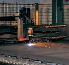
Guía de innovaciones técnicas
                 NSIX-NSIXE
    Guide to technical innovation

     AISLAMIENTO
     El aislamiento de los depósitos se realiza con materiales con alto poder aislante obtenidos sin el uso de CFC
     o HCFC (de acuerdo con las Directivas europeas 2002/95 / CE y 2003/11 / CE). El material tiene una estruc-
     tura de celdas densas (decenas por cm) en las que está contenido un gas de baja conductividad térmica. Los
     aislantes permiten una dispersión de calor reducida, mejores rendimientos de energía y una gestión óptima
     del sistema. Los aislamientos utilizados en nuestros depósitos de agua caliente se dividen en tres tipos:
     •     Poliuretano rígido: reacción al fuego B3 (DIN 4102);
     •     Poliestireno rígido: reacción al fuego Euroklasse E (EN 13163);
     •     Fibra de poliéster ECOFIRE: reacción al fuego de CLASE 1 (UNI 9177); 100% RECICLABLE;
     •     Poliuretano blando;
     •       Todos los depósitos de agua caliente aislados cumplen con los requisitos de las directivas
           2009/125 / CE y 2010 / 30UE sobre eficiencia energética.

     INSULATION
     The tanks are lagged using materials with high insulating capacity, without using CFCs or HCFCs (in ac-
     cordance with European Directives 2002/95/EC and 2003/11/EC). The material has a dense cell structure
     (dozens per cm) containing gas with low thermal conductivity. The insulation ensures reduced heat loss,
     better energy efficiency and optimum system management. Three types of insulation are used on our hot
     water tanks:
     •    Rigid polyurethane: reaction to fire class B3 (DIN 4102);
     •    Rigid polystyrene: reaction to fire class Euroklasse E (EN 13163);
     •    Polyester fibre ECOFIRE: reaction to fire CLASS 1 (UNI 9177); 100% RECYCABLE;
     •    Soft polyurethane.
     •    All the insulated tanks for hot water, comply with the directive 2009/125/CE and 2010/30UE about
          energy efficiency.

      TRATAMIENTO ANTICORROSIVO VITROFLEX®
      El VITROFLEX es una excelente alternativa a la vitrificación. Las pruebas realizadas en un labora-
      torio externo mostraron que los polvos VITROFLEX, después de 1650 horas en la lámpara Amoco,
      no mostraron ningún efecto de formación de ampollas. Nuestra experiencia muestra que 100
      horas en la lámpara Amoco se comparan con un año de funcionamiento. Esto explica por qué el
      tratamiento VITROFLEX brinda seguridad y garantía.
      •    El tratamiento es adecuado para el contacto con el agua potable de acuerdo con la norma-
           tiva europea y el proceso de recubrimiento se resume en los siguientes pasos:
      •    Arenado interno del tanque de agua sanitaria y fosfatación;
      •    Lavado con agua desmineralizada y posterior secado;
      •    Aplicación de la resina epoxi termoendurecible mediante pintura en aerosol;
      •    Horneo en el horno a ~ 240 ° C.

     VITROFLEX® CORROSION-PROOFING
     VITROFLEX is an alternative to vitrification. Tests carried out by an external laboratory have hi-
     ghlighted that VITROFLEX powder, after 1650 hours under an Amoco lamp, showed no effects of
     blistering. Our experience shows that 100 hours under an Amoco lamp is comparable to one year’s
     operation. This explains why VITROFLEX treatment offers guaranteed safety.
     The treatment is suitable for contact with drinking water according to European regulations.
     The coating process involves the following stages:
     •    Sandblasting and phosphating inside the domestic hot water tank;
     •    Washing with demineralised water and then drying;
     •    Application of thermosetting epoxy resin by spray painting;
     •    Baking in a furnace at ~ 240°C.

8
TRATAMIENTO GALVANIZANTE BAÑO CALIENTE
La galvanización es un sistema para proteger el acero del fenómeno de la corrosión.
El recubrimiento de zinc obtenido del tratamiento se adhiere perfectamente a toda la superficie
del tanque y también cubre esquinas incómodas y agujeros muy estrechos, ofreciendo una pro-
tección catódica completa al acero.
Con el tiempo, la disolución del zinc se produce lentamente, obteniendo la ventaja de una vida
útil prolongada del producto.
El acero solo será atacado cuando la cubierta esté completamente desgastada.
El proceso de galvanización en caliente consiste en sumergir el tanque en un baño de zinc fun-
dido, mantenido en promedio a una temperatura de 455 grados; En esta fase, el zinc, además de
cubrir el acero, también ingresa a la aleación con la capa superficial dando resistencia mecánica
y el agarre correcto al material tratado.
HOT DIP GALVANISATION
Galvanisation is a system for protecting steel against corrosion.
The zinc coating created by the treatment adheres perfectly to the entire surface of the tank, also
covering hard-to-access corners and narrow openings, providing complete cathodic protection
on steel.
The zinc dissolves slowly over time, thus extending useful product life.
The steel is attacked only when the coating is completely consumed.
The hot galvanisation process involves dipping the tank in a bath of molten zinc, at an average
temperature of 455 degrees; in this stage the zinc, as well as covering the steel, also alloys with
the surface layer, providing the treated material with mechanical strength and good grip.
TRATAMIENTO DE VITRIFICACIÓN
Tratamiento con esmalte de porcelana, también llamado “VITRIFICACIÓN”, se obtiene con la apli-
cación de una o dos capas (según el caso) de esmalte con características de resistencia al agua
y al vapor, lo que le da al producto tratado una alta protección de la salud y el medio ambiente.
Los productos no tratados están sujetos a corrosión debido a la presencia de oxígeno y sales
minerales disueltas en el agua.
La fiabilidad completa de este tipo de tratamiento se deriva de su composición inorgánica y del
enlace creado entre el esmalte y la superficie del metal.
Después de hornear en el horno a ~ 850 ° C según el método Bayer y DIN 4753.3, el esmalte no
absorbe agua y no conduce iones, por lo tanto, la vitrificación protege la estructura del producto
al 99.9%.
El 0.1% restante (debido a los puntos expuestos) se elimina insertando sistemas de protección
anticorrosivos, como ánodos de sacrificio de magnesio o ánodos con un sistema electrónico
permanente, dentro del producto.
VITRIFICATION
Treatment with vitreous enamel, also called “VITRIFICATION”, involves applying one or two layers
(depending on the situation) of enamel that is both water and steam resistant, giving the treated
product a high level of protection in relation to health and the environment.
Untreated products can be attacked by corrosion due to oxygen and mineral salts dissolved in
the water.
The complete reliability of this type of treatment is due to its inorganic composition and the link
created between the enamel and the metal surface.
After baking in a furnace at around 850°C according to the Bayer method and standard DIN
4753.3, the enamel does not absorb water and does not conduct ions, consequently vitrification
offers 99.9% protection to the structure of the product.
The remaining 0.1% (due to possible uncoated areas) is provided by fitting the product with
corrosion protection systems, such as magnesium sacrificial anodes or anodes with permanent
electronic systems.
9Guía de innovaciones técnicas
NSIX-NSIXE
Guide to technical innovation
ÁNODO DE MAGNESIO Y CON TESTER DE CONTROL
Algunos productos están protegidos internamente contra daños por corrosión mediante un sis-
tema completamente activo con ánodos de magnesio. Para proteger la estructura de acero, el
ánodo de sacrificio se desgasta. Es por esta razón que el estado de desgaste debe verificarse al
menos cada seis meses. El probador le permite realizar esta verificación sin la necesidad de des-
montar el ánodo: con solo presionar el botón en el probador, puede leer en el panel si necesita
reemplazar el ánodo.
MAGNESIUM ANODE AND TESTER
Some products are protected internally against damage due to corrosion by a completely active
system using magnesium anodes. The sacrificial anode is consumed so as to protect the steel
structure. This is why its condition needs to be checked at least every six months. The tester
performs this check without needing to remove the anode: by simply pressing the button on the
tester, the panel will show whether the anode needs to be replaced.
PROTECCIÓN CATÓDICA CORRIENTE IMPRESA (ACI)
Para evitar verificaciones y reemplazos continuos de los ánodos de magnesio, algunos productos pueden
equiparse con un sistema permanente de protección de acero con un ánodo de corriente impresa. Este
sistema garantiza una protección eléctrica constante a lo largo del tiempo mediante el uso de una varilla
de titanio y un potenciostato: el instrumento compara el potencial dentro del tanque en tiempo real con el
potencial teórico y, en consecuencia, emite una corriente necesaria para proteger todo el cilindro de alma-
cenamiento. El sistema no requiere mantenimiento, es absolutamente libre de desgaste y siempre actúa de
manera efectiva. Además, nuestro sistema ACI tiene un consumo actual de menos de 10 kWh / año. También
se puede montar en calderas ya instaladas y en funcionamiento.
IMPRESSED CURRENT CATHODIC PROTECTION (ICCP)
To avoid the need to continuously monitor and replace magnesium anodes, some products can be fitted with
a system for permanent protection of the steel by impressed current anode.
This system guarantees continuous electrical protection over time using a titanium rod and a potentiostat:
the instrument instantly compares the potential inside the tank against the theoretical potential and con-
sequently applies the current needed to protect the entire storage cylinder. The system does not require
maintenance, is not subject to any wear and is always effective. Moreover, our ICCP system has an annual
power consumption of less than 10 kWh.
This system can also be retro-fitted on storage cylinders that are installed and operating.
La corrosión es un fenómeno natural que conduce al deterioro (más o menos rápido) del metal, debido a su
reacción con el entorno que lo rodea.
En los depósitos, la superficie más sensible a la corrosión es la parte en contacto con el agua, ya que, al ser
rica en oxígeno, se alimentan fenómenos electroquímicos que pueden desgastar el material en sí. En este
entorno, se desarrollan corrientes galvánicas, que se desarrollan cuando dos metales diferentes se ponen
en contacto en una solución electrolítica (solo piense en un tanque de acero al carbono con un intercam-
biador de acero inoxidable), o en fenómenos de corrosión generalizados, que ocurren rascar las áreas cató-
dicas o anódicas, en función de la nobleza del material, o la corrosión por oxígeno, que se desarrolla a partir
de la reacción del oxígeno en contacto con el metal. La efectividad del fenómeno depende de los valores
del agua (pH, dureza, etc.) y del tipo de sistema suministrado con el tanque. Para prevenir estos fenómenos,
Sicc Tech lleva a cabo su tratamiento con Vitroflex e inserta ánodos protectores dentro de sus depósitos.
Corrosion is a natural phenomenon that leads to the deterioration (more or less fast) of the metal, due to its
reaction with the environment that surrounds it.
In tanks, the surface most sensitive to corrosion is the part in contact with water, since, being rich in oxygen,
electrochemical phenomena are fed inside which can wear down the material itself. In this environment, gal-
vanic currents develop, which develop when two different metals are put in contact in an electrolytic solution
(just think of a carbon steel tank with a stainless steel exchanger), or generalized corrosion phenomena,
which will scratch cathodic or anodic areas, based on the nobility of the material, or corrosion by oxygen,
which develops from the reaction of oxygen in contact with the metal. The effectiveness of the phenomenon
depends on the water values (pH,
hardness, etc.) and on the type of system supplied with the tank. To prevent
these phenomena, Sicc Tech carries out its Vitroflex treatment and inserts protective anodes inside its tanks.
10INTERCAMBIADORES DE PLACAS
Los intercambiadores de calor de placas inspeccionables están formados por un paquete de placas de acero
inoxidable prensado de alta calidad y juntas NBR.
La conformación particular del canal creado por dos placas permite alcanzar altos coeficientes de inter-
cambio y una alta turbulencia que ayuda a minimizar la acumulación de residuos.
Los intercambiadores son de doble pared y están hechos de placas acopladas, para formar una doble red de
seguridad. Entonces, en caso de agujeros o cortes en la primera placa del par, el fluido fluye lateralmente
evitando la contaminación del segundo circuito.
Nuestros intercambiadores de calor de placas, instalados junto con nuestros depósitos, se destacan por su
alta eficiencia térmica, dimensiones compactas, gran versatilidad, compatibilidad con numerosos fluidos y
peso reducido en comparación con los intercambiadores de haces de tubos. También tienen un buen efecto
de autolimpieza gracias a la alta turbulencia.
PLATE HEAT EXCHANGERS
openable plate heat exchangers are made from a series of very high quality pressed stainless steel
plates and NBR gaskets.
The specific layout of the channel created between two plates ensures high heat exchange coefficients and
a high degree of turbulence, helping minimise the amount of residues accumulated. These are double-wall
heat exchangers made from pairs of plates, with the double wall ensuring a high degree of safety. Indeed, if
the first plate in the pair is punctured or cut, the fluid comes out from the side, avoiding contamination in
the second circuit.
The plate heat exchangers fitted in our storage tanks stand out for their high thermal efficiency, compact
dimensions, versatility, compatibility with numerous fluids and light weight compared to tube bundle heat
exchangers.
The high turbulence created also means they are self-cleaning.
INTERCAMBIADORES TUBULARES EXTRAIBLES
Los intercambiadores de haz de tubos montados en los productos están construidos de tal manera que
aprovechan al máximo los altos coeficientes de intercambio y, al mismo tiempo, aseguran una operación
larga e ininterrumpida. Los intercambiadores de calor extraíbles están formados por un haz de tubos de
acero inoxidable, cobre o acero al carbono galvanizado en caliente, doblados en forma de “U” y expandidos
sobre una placa gruesa. Están diseñados para presiones de hasta 12 bares y para temperaturas de operación
que varían según el tipo de producto (intercambiador de agua o vapor). Se montan con juntas adecuadas
y están aisladas eléctricamente de la caldera por medio de aisladores de PVC. Las juntas utilizadas para los
intercambiadores de agua son de elastómero EPDM resistente al agua, un material elástico con excelentes
características de resistencia a los agentes atmosféricos, excelentes características de resistencia térmica
y rayos UV, resistencia a los cambios de temperatura (-50 / + 125 ° C) y excelentes propiedades mecánicas
(carga de rotura, alargamiento, resistencia al desgarro). Las juntas utilizadas para los intercambiadores de
vapor están hechas de grafito reforzado con una malla de acero inoxidable. Esta construcción particular los
hace particularmente adecuados para soportar altas temperaturas y tensiones mecánicas.
TUBE BUNDLE HEAT EXCHANGERS AND GASKETS
The tube bundle heat exchangers fitted on products are made to gain the maximum possible
benefit form the high heat exchange coefficients and, at the same time, ensure extended interruption-free
operation. The heat exchangers used are removable U-shaped tube bundles made from
stainless steel, copper or hot galvanised carbon steel, expanded onto thick metal plates. They are designed
to operate at pressures up to 12 bars and temperatures that vary according to the type of product (heat
exchangers for water or steam). They are fitted with suitable gaskets and electrically insulated from the
storage cylinders by PVC insulators. The gaskets used on water heat exchangers are made from impermeable
EPDM elastomer, an elastic material with outstanding resistance to the weather, heat and UV radiation, a
very wide range of operating temperatures (-50 / +125°C) and excellent mechanical properties (breaking
strength, elongation, tear strength). The gaskets used on steam heat exchangers are made from graphite
reinforced with stainless steel mesh. This specific constructional solution makes them especially suitable for
resisting high temperatures and mechanical stress.
11EVP Interacumuladores con intercambiador extraíble
Storage tank with removable heat exchanger
Los productos de la serie EVP son interacumuladores para la producción y
almacenamiento de agua caliente sanitaria. Los intercambiadores de calor son
con haz de tubos extraíble, con tubos de acero inoxidable expandidos sobre
placa de acero tratada con VITROFLEX.
Un gran potencial de intercambio combinado con pérdidas de carga
insignificantes hacen el compromiso ideal entre la potencia instalada y el
volumen de agua caliente acumulados, son ideales para sistemas sanitarios
donde la extracción de agua caliente alcanza picos de alta demanda (centros
deportivos, hospitales, piscinas, instalaciones civiles centralizadas,...).
The EVP series products are storage tanks for the production and storage
of domestic hot water. The heat exchangers used are removable U-shaped
tube bundles, made by stainless steel tubes expanded onto steel plates with
VITROFLEX treatment. These storage tanks, with high heat exchange capacity
and low pressure drop, represents the best compromise between installed power
and volume of hot water stored, making them ideal for connection to domestic
hot water systems where delivery of hot water has very high peaks (sports
centres, hospitals, swimming pools, centralised residential systems,...).
Todos los depósitos aislados cumplen con los requisitos de las directi-
vas 2009/125/CE y 2010/30/UE sobre la eficiencia energética
All the insulated tanks, comply with the directive 2009/125/CE and
2010/30UE about energy efficiency
CARACTERÍSTICAS TÉCNICAS TECHNICAL FEATURES
Construcción Acero al carbono de alta calidad
del acumulador High quality carbon steel
Storage tank construction
Tratamiento interno Tratamiento anticorrosivo VITROFLEX adecuado para agua para uso alimentario según CE, D.M. 174
Inside treatment VITROFLEX corrosion-proofing suitable for drinking water in accordance with EC directives
ECOFIRE, 300÷1000 lt. espesor 100 mm
ECOFIRE, 300÷1000 lt. 100 mm thick
Aislamiento extraíble ECOFIRE, 1500÷2000 lt. espesor 130 mm
Removable Insulation ECOFIRE, 1500÷2000 lt. 130 mm thick
ECOFIRE, 2500÷5000 lt. espesor 100 mm
ECOFIRE, 2500÷5000 lt. 100 mm thick
Recubrimiento externo PVC acoplado
Outside covering Laminated PVC
Acumulador Pmax 8 bar - Tmax 90°C
Storage tank
Pmax 12 bar - Tmax 110°C
Intercambiador Acero inoxidable extraíble insertado en la misma boca de hombre
Heat exchanger Removable stainless steel
Accesorios estándar Ánodos de magnesio con tester de control
Standard accessories Magnesium anode/anodes with tester
Garantía 3 años
Warranty 3 years
El modelo EVP VERSIÓN ALTURA REBAJADA está disponible para instalaciones en ambientes con una altura máxima de uso de
2.510 mm (a consultar)
The EVP LOWERED VERSION can be used for installation in rooms where the maximum height available is 2.510 mm (consulting)
Productos que cumplen con la Directiva 2014/68 / UE PED (Art.4 Par.3)
Products complying with the directive 2014/68/UE PED (Art.4 Par.3)
12Uso: agua caliente sanitaria Se puede combinar con
Use: domestic hot water Combined with:
A.C.S.
Ejemplo de la instalación Example of a system Diseño técnico Technical drawing
e2 z
z s e2 - x
hs
AN2 45° 45°
h2
RC
RC - e1
st s - AN2 - st - AN3 - AN1
RE hst
RE - Sc - Sc1
H d
AN3
H5 h3
Sc
a1
H4 a2
H3 e1 AN1
h1
HSc1
H2
H1
x
Ds
Dc
a1 Entrada del circuito primario AN3 Anodo 300÷800 lt s Conexión de sonda auxiliar
Primary circuit inlet Anode 300÷800 lt Auxiliary probe fitting
a2 Salida circuito primario AN1-AN2 Anodos 1000÷5000 lt st Conexión de la sonda de temperatura
Primary circuit inlet Anodes 1000÷5000 lt Temperature probe fitting
e1 Entrada agua sanitaria RE Conexión de resistencia eléctrica RC Recirculación
Domestic water inlet Electric heater fitting Ricirculation
e2 Sadida agua sanitaria Z Conexión auxiliar 1500÷5000 X Desagüe
Domestic water outlet Auxiliary fitting 1500÷5000 Drain
CONEXIONES CONNECTIONS
lt
a1 a2 e1 e2 AN1÷AN3 RE Z s st RC X
300÷500 G1"-F G1"-F G1"1/4-F G1"1/2-F G1"1/4-F G2"-F - G1/2"-F G1/2"-F G1"-F G1"1/4-F
750÷1000 G2"-F G2"-F G1"1/4-F G1"1/2-F G1"1/4-F G2"-F - G1/2"-F G1/2"-F G1"-F G1"1/4-F
1500÷5000 G2"-F G2"-F G3"-F G3"-F G1"1/4-F G2"-F G2"-F G1/2"-F G1/2"-F G1"-F G3"-F
MEDIDAS SIZES (mm)
Peso
Sondas Ánodos Weight
lt Dc
Probes Anodes
Ds H H1 H2 H3 H4 H5 HSc1 d (Kg)
EVPXX hst hs h1 h2 h3
300 550 750 1580 165 390 830 930 - 480 830 1230 - - 700 1770 75
500 650 850 1895 155 410 850 1050 - 500 850 1400 - - 720 2095 105
750 790 990 1940 145 430 1070 1170 - 560 1070 1520 - - 920 2200 140
1000 790 990 2190 145 430 1070 1170 - 610 1070 1670 420 1370 - 2420 160
1500 950 1210 2530 185 485 1110 1310 2135 670 1110 1960 460 1560 - 2860 255
2000 1100 1360 2580 170 495 1220 1520 2145 705 1220 1970 470 1570 - 2975 320
2500 1250 1450 2605 150 520 1245 1545 2170 730 1245 1995 495 1595 - 3000 335
3000 1250 1450 2795 150 520 1245 1695 2370 730 1245 2245 495 1745 - 3170 360
4000 1400 1600 2895 155 570 1285 1735 2410 770 1285 2285 535 1785 - 3330 545
5000 1600 1800 2930 130 585 1300 1750 2425 785 1300 2300 550 1800 - 3460 635
13EVP Interacumulador con intercambiador extraíble
Storage tank with removable heat exchanger
RENDIMIENTO PERFORMANCE
(1) (2) (3) (3)
1
lt m2 KW l/h min l/h l/10’
300 0.75 27 2322 45 704 254
500 1 32 2752 63 834 366
750 1.5 56 4816 57 1459 607
1000 2 74 6364 54 1929 776
1500 3 94 8084 64 2450 1090
2000 4 150 12900 54 3909 1561
2500 5 174 14964 58 4535 1892
3000 6 200 17200 60 5212 2232
4000 8 289 24854 56 7532 3073
5000 10 336 28896 60 8756 3732
(1) Potencia térmica del intercambiador de calor calculada suponiendo una temperatura de entrada / salida del circuito primario de 80/70 ° C y una
temperatura de entrada de agua caliente sanitaria de 12 ° C.
(2) Tiempo requerido para elevar la temperatura de la entrada de agua sanitaria, 12 ° C, a la temperatura de almacenamiento de 60 ° C.
(3) Cantidad de agua caliente sanitaria disponible a la temperatura de funcionamiento de 45 ° C de forma continua o en los primeros 10 minutos.
(1) Heat exchanger output calculated assuming a primary circuit inlet/outlet temperature of 80/70°C and a DHW inlet temperature of 12°C.
(2) Time needed to increase the domestic water inlet temperature, 12°C, to the storage temperature of 60°C.
(3) Quantity of domestic hot water available at a delivery temperature of 45°C, continuously or in the first 10 minutes.
TABLA DE INTERCAMBIADORES HEAT EXCHANGER TABLE
lt 300 500 750 1000 1500 2000 2500 3000 4000 5000
Estándar Sc1 Sc1 Sc1 Sc1 Sc1 Sc1 Sc1 Sc1 Sc1 Sc1
Standard
(m2) 0.75 1 1.5 2 3 4 5 6 8 10
1 0.75 2 1.5 1.5 5 4 4 4 4
Opcional 3 3 2 6 6 5 5 5
(m2) 6 6
8
DATOS INTERCAMBIADORES HEAT EXCHANGER DATA
0.75 1 1.5 2 3 4 5 6 8 10
m2
27 32 56 74 94 150 174 200 289 336
KW
4 5 8.5 10.5 14 19 22 24.8 33 40
lt
300 300 380 430 430 430 430 430 430 430
Capacidad de almacenamiento (lt.) Superficie de intercambio (m2) Potencia de intercambio (Kw)
lt Storage tank capacity (lt.) m2 Heat exchanger surface (m2) KW Heat exchanger power (Kw)
(2) (1)
1 Caudal primario (l/h) Tiempo de puesta en funcionamiento (min.) Caudal (l/h)
l/h Primary flow-rate (l/h) min TIme to reach temperature (min.) l/h DHW flow-rate (l/h)
(3)
Caudal de ACS en los primeros 10 min. Intercambiador contenido de agua (lt.) Diámetro de la brida del intercambiador
l/10’ DHW flow-rate in the first 10 min. lt Heat exchangercapacity (lt.) Heat exchanger diameter flange
14EVP LOW Interacumuladores con intercambiador extraíble VERSIÓN ALTURA REBAJADA
Storage tank with removable heat exchanger LOWERED VERSION
A.C.S.
Los productos de la serie EVP LOW son interacumuladores para producción
y almacenamiento de agua caliente sanitaria apta para instalaciones en
habitaciones con altura máxima utilizable hasta 2500 mm.
Disponible para capacidades a partir de 1500 lt.
The EVP LOW series are storage tanks for the production and storage of
domestic hot water, suitable for installation in rooms with a maximum
available height of 2500 mm.
Available with capacities starting from 1500 litres.
Todos los depósitos aislados cumplen con los requisitos de las directi-
vas 2009/125 / CE y 2010/30 / UE sobre eficiencia energética
All the insulated tanks, comply with the directive 2009/125/CE and
2010/30UE about energy efficiency
CARACTERÍSTICAS TÉCNICAS TECHNICAL FEATURES
Construcción Acero al carbono de alta calidad
de acumulador High quality carbon steel
Storage tank construction
Tratamiento interno Tratamiento anticorrosivo VITROFLEX adecuado para agua para uso alimentario según CE, D.M. 174
Inside treatment VITROFLEX corrosion-proofing suitable for drinking water in accordance with EC directives
ECOFIRE, 1500÷2000 lt. espesor 130 mm
Aislamiento extraíble ECOFIRE, 1500÷2000 lt. 130 mm thick
Removable Insulation ECOFIRE, 2500÷5000 lt. espesor 100 mm
ECOFIRE, 2500÷5000 lt. 100 mm thick
Revestimiento externo PVC acoplado
Outside covering Laminated PVC
Acumulación Pmax 8 bar - Tmax 90°C
Storage tank
Pmax 12 bar - Tmax 110°C
Intercambiador Acero inoxidable extraíble insertado en la misma boca de hombre
Heat exchanger Removable stainless steel
Accesorios estándar Ánodo/s de magnesio con tester de control
Standard accessories Magnesium anode/anodes with tester
Garanzia 3 años
Warranty 3 years
Productos que cumplen con la directiva 2014/68/UE PED (Art.4 Par.3)
Products complying with the directive 2014/68/UE PED (Art.4 Par.3)
15Use: domestic hot waterNSIX-NSIXE
Uso: agua caliente sanitaria Se puede combinar con:
Combined with:
Ejemplo de instalación Example of a system Diseño técnico Technical drawing
e2 z
d
z
s hs e2 - x
RC
RE AN2 h2
Sc st hst
H 45° 45°
max a1
H5 a2
AN1 h1 RC - e1 s - AN2
H4 e1 st - AN1
H3
HSc RE - Sc
H2
H1
x
Ds
Dc
a1 Entrada circuito primario AN1-AN2 Anodos st Conexión sonda temperatura
Primary circuit inlet Anodes Temperature probe fitting
a2 Salida circuito primario RE Conexión resistencia eléctrica RC Recirculación
Primary circuit inlet Electric heater fitting Ricirculation
e1 Entrada agua sanitaria Z Conexión auxiliar X Desagüe
Domestic water inlet Auxiliary fitting Drain
e2 Salida agua sanitaria s Conexión sonda auxiliar
Domestic water outlet Auxiliary probe fitting
CONEXIONES CONNECTIONS
lt
a1 a2 e1 e2 AN1÷AN3 RE Z s st RC X
1500÷5000 G2"-F G2"-F G3"-F G3"-F G1"1/4-F G2"-F G2"-F G1/2"-F G1/2"-F G1"-F 3"
MEDIDAS SIZES (mm)
Peso
Dc Sondas Ánodos
lt Probes Anodes Weight
Ds Hmax H1 H2 H3 H4 H5 HSc d m2 (Kg)
EVPXX hst hs h1 h2
LOW
1500 1100 1360 2080 170 495 1120 1220 1570 705 1120 1570 470 1370 2545 3 255
2000 1250 1510 2080 150 520 1080 1395 1570 730 1080 1545 495 1345 2630 4 320
2500 1400 1600 2000 155 560 1120 1185 1410 770 985 1385 535 1285 2585 5 335
3000 1600 1800 2000 130 575 1085 1150 1400 785 1085 1400 550 1200 2715 6 360
3000 B 1400 1600 2300 155 570 1185 1385 1810 770 1185 1685 535 1485 2825 6 360
4000 1900 2100 2000 130 640 1200 1345 1390 850 1065 1380 615 1295 2925 8 454
4000 B 1600 1800 2500 130 585 1300 1250 1925 785 1300 1800 550 1500 3100 8 454
5000 1900 2100 2250 120 630 1190 1455 1655 840 1190 1605 605 1405 3100 10 635
16EVP LOW Interacumuladores con intercambiador extraíble versión ALTURA REBAJADA
Storage tank with removable heat exchanger LOWERED VERSION
A.C.S.
RENDIMIENTO PERFORMANCE
(1) (2) (3) (3)
1
lt m2 KW l/h min l/h l/10’
1500 3 94 8084 64 2450 1090
2000 4 150 12900 54 3909 1561
2500 5 174 14964 58 4535 1892
3000 6 200 17200 60 5212 2232
4000 8 289 24854 56 7532 3073
5000 10 336 28896 60 8756 3732
(1) Potencia térmica del intercambiador calculado suponiendo una temperatura de entrada / salida del circuito primario de 80/70 ° C
y una temperatura de entrada de agua caliente sanitaria de 12°C
(2) Tiempo requerido para elevar la temperatura de la entrada de agua sanitaria, 12 ° C, a la temperatura de almacenamiento de 60 ° C.
(3) Cantidad de agua caliente sanitaria disponible a la temperatura de funcionamiento de 45 ° C de forma continua o en los primeros 10 minutos.
(1) Heat exchanger output calculated assuming a primary circuit inlet/outlet temperature of 80/70°C and a DHW inlet temperature of 12°C.
(2) Time needed to increase the domestic water inlet temperature, 12°C, to the storage temperature of 60°C.
(3) Quantity of domestic hot water available at a delivery temperature of 45°C, continuously or in the first 10 minutes.
TABLA INTERCAMBIADORES HEAT EXCHANGER TABLE
lt 1500 2000 2500 3000 4000 5000
Estándar Sc1 Sc1 Sc1 Sc1 Sc1 Sc1
Standard
(m2) 3 4 5 6 8 10
1.5 5 4 4 4 4
Opcional 2 6 6 5 5 5
(m2) 6 6
8
DATOS INTERCAMBIADORES HEAT EXCHANGER DATA
1.5 2 3 4 5 6 8 10
m2
56 74 94 150 174 200 289 336
KW
8.5 10.5 14 19 22 24.8 33 40
lt
380 380 380 430 430 430 430 430
Capacidad almacenamiento (lt.) Superficie de intercambio (m2) Potencia de intercambio (Kw)
lt Storage tank capacity (lt.) m2 Heat exchanger surface (m2) KW Heat exchanger power (Kw)
(2) (1)
1 Caudal primario Tiempo para alcanzar la temperatura Portata ACS (l/h)
l/h Primary flow-rate (l/h) min TIme to reach temperature (min.) l/h DHW flow-rate (l/h)
(3) Diámetro del intercambiador
Caudal de ACS en los primeros 10 min. Contenido Intercambiador de agua (lt.)
l/10’ de calor brida
DHW flow-rate in the first 10 min. lt Heat exchangercapacity (lt.)
Heat exchanger diameter flange
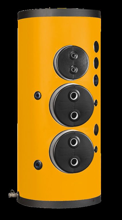
17116 Acumuladores de agua caliente sanitaria
Domestic hot water storage tanks
Los productos de la serie 116 son acumuladores de almacenamiento para
agua caliente sanitaria. Ideal en sistemas donde la extracción de agua
caliente alcanza picos de alta demanda y generalmente están conectados
a intercambiadores de calor externos, con mayor frecuencia de placas
(piscinas, centros deportivos, hoteles, campings).
The 116 series products are domestic hot water storage tanks.
These are ideal in systems where the delivery of hot water has very high
peaks and are generally connected to external heat exchangers, more
commonly plate heat exchangers (swimming pools, sports centers, hotels,
camping)
Todos los depósitos aislados cumplen con los requisitos de las directi-
vas 2009/125 / CE y 2010/30 / UE sobre eficiencia energética
All the insulated tanks, comply with the directive 2009/125/CE and
2010/30UE about energy efficiency
CARATERÍSTICAS TÉCNICAS TECHNICAL FEATURES
Construcción acumulador Acero al carbono de alta calidad
Storage tank construction High quality carbon steel
Tratamiento interno Tratamiento anticorrosivo VITROFLEX adecuado para agua para uso alimentario según CE, D.M. 174
Inside treatment VITROFLEX corrosion-proofing suitable for drinking water in accordance with EC directives
ECOFIRE, 300÷1000 lt. espesor 100 mm
ECOFIRE, 300÷1000 lt. 100 mm thick
Aislamiento extraíble ECOFIRE, 1500÷2000 lt. espesor 130 mm
Removable Insulation ECOFIRE, 1500÷2000 lt. 130 mm thick
ECOFIRE, 3000÷5000 lt. espesor 100 mm
ECOFIRE, 3000÷5000 lt. 100 mm thick
Revestimiento externo PVC acoplado
Outside covering Laminated PVC
Acumulador Pmax 8 bar - Tmax 90°C
Storage tank
Accessorios estándard Ánodo/s de magnesio con tester de control
Standard accessories Magnesium anode/anodes with tester
Garantía 3 años
Warranty 3 years
Está disponibile el modello 116 VERSIÓN ALTURA REBAJADA para instalaciones en ambientes con una altura máxima de uso de
2.510 mm (a consultar)
The 116 LOWERED VERSION can be used for installation in rooms where the maximum height available is 2.510 mm (consulting)
116PX 116PX
VITROFLEX VITROFLEX
Aislamiento flexible espesor 100 mm Aislamiento flexible espesor 130 mm
Flexible insulation 100 mm thick Flexible insulation 130 mm thick
Clase Clase
Energética Energética
Código Código
lt Code € lt Code €
300 116PX0300 C 1500 116PX1500 C
500 116PX0500 C 2000 116PX2000 C
750 116PX0800 C
1000 116PX1000 C
3000 116PX3000 -
4000 116PX4000 -
5000 116PX5000 -
Lista de precios de accesorios y repuestos en página 29 Accessories and spare parts price list available at page 29
Productos que cumplen con la directiva 2014/68/UE PED (Art.4 Par..3)
Products complying with the directive 2014/68/UE PED (Art.4 Par.3)
18Uso: agua caliente sanitaria Se puede combinar con:
Use: domestic hot water Combined with:
A.C.S.
Ejemplo de instalación Example of a system Diseño técnico Technical drawing
e2
45°
RC-e1
z
e2-x
s1 hs1
RE z-s1-RE-AN2-s2
a1-a2 AN3-st-AN1
a1 AN2 h2
45° 45°
H RC d s2 hs2
H5 AN3 h3
d1
HSc
st hst H4
AN1 h1
H3 a2-e1
H2
H1
x
Ds
Dc
a1 Entrada circuito primario AN3 Ánodo 300÷800 lt s1-s2 Conexión sonda auxiliar
Primary circuit inlet Anode 300÷800 lt Auxiliary probe fitting
a2 Salida circuito primario AN1-AN2 Ánodos 1500÷5000 lt st Conexión sonda temperatura
Primary circuit inlet Anodes 1500÷5000 lt Temperature probe fitting
e1 Entrada agua sanitaria RE Conexión resistencia eléctrica RC Recirculación
Domestic water inlet Electric heater fitting Ricirculation
e2 Salida agua sanitaria Z Conexión auxiliar 1500÷5000 lt X Desagüe
Domestic water outlet Auxiliary fitting 1500÷5000 lt Drain
CONEXIONES CONNECTIONS
lt
a1 a2 e1 e2 AN1÷AN3 RE Z s1 - s2 st RC X
300÷1000 G1”1/4-F G1”1/4-F G1"1/4-F G1"1/2-F G1"1/4-F G2"-F - G1/2"-F G1/2"-F G1"-F G1"1/4-F
1500÷5000 G1”1/4-F G1”1/4-F G3"-F G3"-F G1"1/4-F - G2"-F G1/2"-F G1/2"-F G1"-F G3"-F
MEDIDAS SIZES (mm) Peso
Weight
Sondas Ánodos
lt Dc
Probes Anodes (Kg)
Ds H H1 H2 H3 H4 H5 HSc d
116PX hst hs1 hs2 h1 h2 h3 116PX
300 550 750 1580 165 390 930 980 - 880 525 1280 - - - 700 1770 55
500 650 850 1895 155 410 1050 1190 - 540 1500 - - - 720 2095 84
750 790 990 1940 145 430 1170 1170 - 585 1520 - - - 920 2200 106
1000 790 990 2190 145 445 1170 1570 - 655 1720 - 420 1170 - 2420 125
1500 950 1210 2530 185 485 1310 - 2135 710 1960 1150 460 1510 - 2860 235
940
2000 1100 1360 2580 170 495 1320 - 2145 720 1970 1205 470 1520 - 2975 280
3000 1250 1450 2795 150 520 1345 - 2370 745 2245 1230 495 1745 - 3170 303
4000 1400 1600 2895 155 560 1385 - 2410 785 2285 1270 535 1785 - 3330 477
5000 1600 1800 2930 130 575 1400 - 2425 800 2300 1285 550 1800 - 3460 560
BOCA DE HOMBRE: 410 X 510 mm. de 1.000 L a 5.000 L.
19116 LOW Acumuladores ACS VERSIÓN ALTURA REBAJADA
DHW storage tanks lowered version
Los productos de la serie 116 LOW son acumuladores de almacenamiento
para agua caliente sanitaria adecuada para instalaciones en ambientes con
altura máxima utilizable de hasta 2500 mm.
Ideal en sistemas donde la extracción de agua caliente alcanza picos de
alta demanda y generalmente están conectados a intercambiadores de
calor externos, en su mayoría de placas (piscinas, centros deportivos,
hoteles, campings).
Disponible para capacidades desde 1500 lt
The 116 LOW series products are domestic hot water storage tanks, suitable
for installation in rooms with a maximum available height of 2500 mm.
These are ideal in systems where the delivery of hot water has very high
peaks and are generally connected to external heat exchangers, more
commonly plate heat exchangers (swimming pools, sports centers, hotels,
camping).
Available with capacities starting from 1500 litres.
Todos los depósitos aislados cumplen con los requisitos de las directi-
vas 2009/125 / CE y 2010/30 / UE sobre eficiencia energética
All the insulated tanks, comply with the directive 2009/125/CE and
2010/30UE about energy efficiency
CARACTERÍSTICAS TÉCNICAS TECHNICAL FEATURES
Construcción Acero al carbón de alta calidad
del acumulador High quality carbon steel
Storage tank construction
Trattamento interno Tratamiento anticorrosivo VITROFLEX adecuado para agua para uso alimentario según CE, D.M. 174
Inside treatment VITROFLEX corrosion-proofing suitable for drinking water in accordance with EC directives
ECOFIRE, 1500÷2000 lt. espesor 130 mm
Tratamiento interno ECOFIRE, 1500÷2000 lt. 130 mm thick
Removable Insulation ECOFIRE, 2500÷5000 lt. espesor 100 mm
ECOFIRE, 2500÷5000 lt. 100 mm thick
Aislamiento extraíble PVC acoplado
Outside covering Laminated PVC
Acumulador Pmax 8 bar - Tmax 90°C
Storage tank
Accesorios estándar Ánodo/s de magnesio con tester de control
Standard accessories Magnesium anode/anodes with tester
Garantía 3 años
Warranty 3 years
116PX LOW 116PX LOW
VITROFLEX VITROFLEX
Aislamiento flexible espesor 100 mm Aislamiento flexible espesor 130 mm
Flexible insulation 100 mm thick Flexible insulation 130 mm thick
Clase Clase
Energética Energética
Código Código
lt Code € lt Code €
2500 116PX02500SB - 1500 116PX01500SB C
3000 116PX03000SB - 2000 116PX02000SB C
3000B 116PX03000SBB -
4000 116PX04000SB -
4000B 116PX04000SBB -
5000 116PX05000SB -
Lista de precios de accesorios y repuestos en página 29
Accessories and spare parts price list available at page 29
Productos que cumplen con la directiva 2014/68/UE PED (Art.4 Par.3)
Products complying with the directive 2014/68/UE PED (Art.4 Par.3)
20También puede leer