TÉCNICA QUIRÚRGICA Sistema de Abordaje Lateral para la Fusión Lumbar XLOCK - Lateral Lumbar Interbody Fusion XLOCK - X-LOCK Técnica ...
←
→
Transcripción del contenido de la página
Si su navegador no muestra la página correctamente, lea el contenido de la página a continuación
TÉCNICA
    QUIRÚRGICA   SURGICAL TECHNIQUE

  Sistema de Abordaje Lateral
para la Fusión Lumbar XLOCK
         Lateral Lumbar Interbody Fusion XLOCK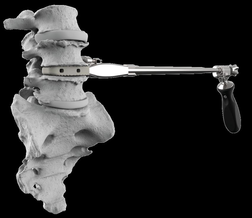
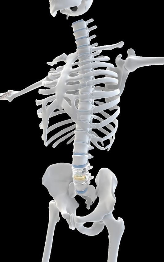
Solución integral para la
fusión intersomática lumbar
con abordaje lateral.
Comprehensive solution for lateral lumbar interbody fusion.

El abordaje lateral es una técnica mínimamente invasiva
que evita tanto los vasos sanguíneos anteriores como las
estructuras neurales y óseas posteriores.
The lateral approach is a minimally invasive technique that avoids trauma to the anterior
blood vessels as well as to the posterior neural and bone structures.

PAG. 01
Índice Index
PASO A PASO Step by Step
Paso 01          Posición del paciente.                                                                                                                                               03
Step 01          Patient position.

Paso 02          Armado de asistente para soporte del sistema retractor.                                                                                                              04
Step 02          Assembly of retractor holder.

Paso 03          Incisión, liberación y disección de partes blandas.                                                                                                              04 - 05
Step 03          Incision, release and dissection of soft tissue.

Paso 04          Tubos dilatadores.                                                                                                                                                   05
Step 04          Dilation tubes.

Paso 05          Armado del aro retractor.                                                                                                                                        06 - 07
Step 05          Assembly of retractor ring.

Paso 06          Discectomía y preparación de platillos vertebrales.                                                                                                              08 - 10
Step 06          Discectomy and preparation of vertebral endplates.

Paso 07          Selección de implante de prueba.                                                                                                                                  11 - 16
Step 07          Selection of implant trial.

Paso 08          Armado del colocador de implante y carga de la caja intersomática.                                                                                                17 - 18
Step 08          Assembly of implant inserter and loading of intersomatic cage.

Paso 09          Preparación de la caja intersomática.                                                                                                                                 19
Step 09          Preparation of intersomatic cage.

Paso 10          Inserción de caja.                                                                                                                                               20 - 21
Step 10          Cage insertion.

Paso 11          Inserción de la placa de anclaje.                                                                                                                                22 - 23
Step 11          Insertion of anchoring plate.

Paso 12          Control final y desarme del colocador.                                                                                                                                24
Step 12          Final checkup and inserter disassembly.

EXTRACCIÓN Removal
Extracción de la placa de anclaje y caja intersomática.                                                                                                                           25 - 27
Removal of anchoring plate and intersomatic cage.

Advertencia         Esta descripción de la técnica quirúrgica no es suficiente para su aplicación clínica inmediata. Se recomienda el aprendizaje práctico con
Warning             un cirujano experimentado.
                    This description of the surgical technique is not enough for immediate use in clinical application. Hands-on training with an experienced surgeon is highly
                    recommended.

PAG. 02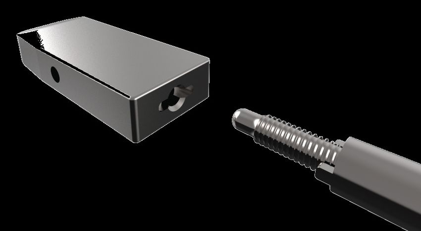
Posición del paciente                                                                                                                                        Paso 01
Patient position                                                                                                                                                       Step 01

El paciente se coloca en posición decúbito lateral (debe ser asegurado
en su lugar con cinta adhesiva).
La mesa está flexionada para aumentar la distancia entre las costillas y la
cresta ilíaca.
Place the patient in a lateral decubitus (90°) position (the patient should be secured to the table with
adhesive tape).
The surgical table is retroflexed to increase the distance between the iliac crest and the ribs.

Precaución              Evite puntos indebidos de presión al colocar y asegurar al
Caution                 paciente.
                        Avoid undue pressure when placing and securing the patient.

Nota                    Si está previsto trabajar con neuromonitorización, el
Note                    neurofisiólogo o el auxiliar de neuromonitorización deben
                        aplicar todos los electrodos necesarios antes de proceder a
                        la colocación del paciente.
                        If neuromonitoring is to be used, a neurophysiologist or neuromonitoring
                        technician should apply electrodes to the patient prior to patient positioning.

El abordaje lateral utiliza una técnica de una o dos incisiones. Marcar el espacio discal a trabajar mediante radioscopia
utilizando la cruz de marca vertebral. Marcar la piel apropiadamente. Para procedimientos multinivel es posible que se
requiera más de una incisión en la piel.
Se colocara una clavija de guía para asegurar el paso de los dilatadores y el sistema del aro retractor.

The lateral approach uses one or two incisions. Mark the distal space with X-rays using a vertebral marking cross. Mark the skin properly. For multilevel procedures, more than one
skin incision may be required.
A guide pin is inserted to secure the passage of dilation tubes and the retractor ring set.

Se obtiene una imagen fluoroscópica para garantizar que la
incisión lateral directa se ubique en el espacio discal que se
tiene por objetivo.
A fluoroscopic image is obtained to ensure that the direct lateral incision is placed in
                                                                                                                              Cruz de marca vertebral
the target disc space.                                                                                                            Vertebral marking cross

PAG. 03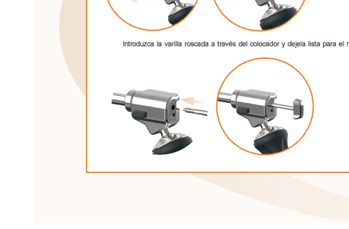
Armado de asistente para soporte del sistema retractor                                                                                                  Paso 02
Assembly of retractor holder                                                                                                                              Step 02

Colocar la morsa de fijación a la camilla, esta sirve de sostén al brazo
articulado en el cual se ensambla el aro retractor.
Attach the clamp to the operating table to support the articulating arm on which the retractor ring is
mounted.

                                                                                                                                        Brazo
                                                                                                                                     Articulating arm

                                          Morsa de fijación
                                          Clamp

Incisión, liberación y disección de partes blandas                                                                                                      Paso 03
Incision, release and dissection of soft tissue                                                                                                           Step 03

Después de hacer una única incisión en la piel, las capas de grasa subcutánea se disecan hasta que se alcanza la musculatura
abdominal.
La fascia oblicua externa será la primera capa encontrada y es la única que necesitará tener una incisión aguda.
Un bisturí largo se usa para atravesar las fibras externas de los músculos oblicuo, oblicuo interno y transversal.
Toda disección se realiza en línea con las fibras musculares (corren en direcciones opuestas).
After making an incision in the skin, the subcutaneous fat tissue layer is dissected, and the abdominal muscles should be visible.
The external oblique fascia is the first layer to be found and the only one that will require a deep incision.
A long scalpel is used to cut through the external fibers of the oblique, internal oblique and transverse muscles.
Any dissection is made in line with the muscle fibers (they run in opposite directions).

Nota                    Utilizar bisturí prolongado para realizar las incisiones.
Note                    Use a long scalpel for incisions.

                                                                            Clavija Ø 1.5mm - Punta roma
                                                                                       Blunt 1.5mm pin

PAG. 04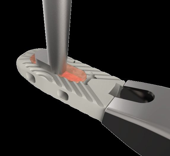
Incisión, liberación y disección de partes blandas                                                                                                                                        Paso 03
Incision, release and dissection of soft tissue                                                                                                                                                       Step 03

Una vez dentro del espacio retroperitoneal, utilice el dedo índice para seguir la pared posterior del abdomen interno hasta
que el músculo psoas pueda ser visualizado. Usar el dedo para barrer el contenido peritoneal.
Once the retroperitoneal space has been entered, use your forefinger to palpate the internal abdomen posteriorly until the psoas is visible. Use your finger to sweep the peritoneum.

                                                                                 14mm
Pueden servirse de valvas
inclinadas (de 14 y 20 mm)
para la apertura del canal de
abordaje.                                                                        20mm
Slanted blades (14 and 20 mm) may be used
to open the approach channel.

Palpando el músculo cuadrado, seguido de la punta del proceso transversal
y finalmente el músculo psoas verificará que se está ingresando el plano
retroperitoneal correcto y asegura que el peritoneo no se vea
comprometido.
Palpating the quadratus muscle, then the tip of the transverse space and finally the psoas muscle, confirm that
the proper retroperitoneal space has been entered and that the peritoneum is not compromised.

Tubos dilatadores                                                                                                                                                                        Paso 04
Dilation tubes                                                                                                                                                                                        Step 04

Introduzca una clavija punta roma a través del psoas, por el centro de la zona segura, hasta llegar al anillo fibroso del disco
intervertebral afectado.
Determine la posición de la clavija bajo control radioscópico en proyección lateral.
Separe el músculo psoas insertando el dilatador de menor diámetro sobre la clavija. Repita el proceso con el dilatador de
diámetro inmediatamente superior, hasta conseguir la dilatación necesaria. Determine bajo control radioscópico la posición
del dilatador. Retire la clavija.
Insert a blunt pin through the psoas muscle, at the center of the safe zone, to reach the fibrous tissue ring of the intervertebral disc involved.
Determine the position of the pin with x-ray control in a lateral view.
Separate the psoas muscle inserting the dilation tube with the lowest diameter into the pin. Repeat the procedure using the dilation tube with the diameter immediately above,
until reaching the dilatation required. With radioscopic control, determine the dilation tube position. Remove the pin.

                                                                                                                           Si tiene previsto utilizar neuromonitorización, monte la sonda de
                                                                                                                           estimulación monopolar.
                                                                                                                           Conecte el cable al mango y éste al extremo proximal de la sonda de
                                                                                                                           estimulación monopolar. Pase el extremo libre del cable al
                                                                                                                           neurofisiólogo o auxiliar de neuromonitorización.
                                                120

                                                            100
                                                      110

                                                                  90
                                                                       80
                                                                            70

                                                                                      50
                                                                                           40
                                                                                                30
                                                                                                     20
                                                                                 60

                                                                                                                           (El primer tubo de dilatación en metálico)
                                                                                                                           If neuromonitoring is selected for use, insert a monopolar probe.
                                                                                                                           Connect the cable previously connected to the handle to the proximal end of the monopolar
                                                                                                                           probe. Pass the free end of the cable to the neurophysiologist or neuromonitoring
                                                                                                                           technician.(The first metal dilation tube).

Nota                    Los tubos dilatadores poseen una regla que determinará el largo de las valvas a ensamblar en el aro retractor
Note                    The dilation tubes have a ruler to determine the length of the blades to be mounted on the retractor ring.

PAG. 05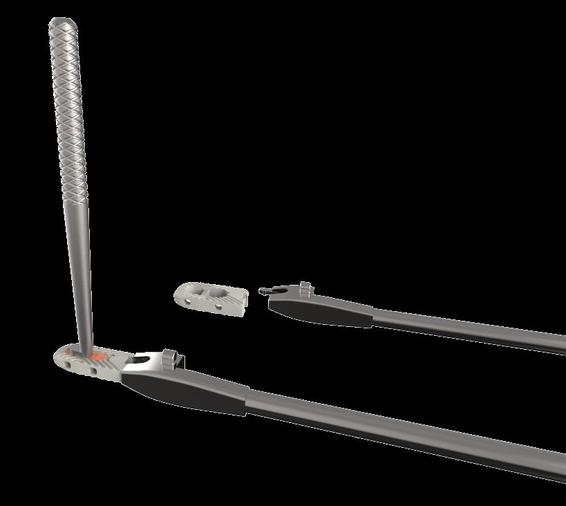
Armado del aro retractor                                                                                                                                   Paso 05
Assembly of retractor ring                                                                                                                                            Step 05

El retractor está asegurado a la mesa de operaciones por medio del brazo articulado previamente colocado.
Introduzca las trabas del aro en el brazo articulado y apriete la roseta de fijación del brazo en sentido horario.
Determine la longitud adecuada de las valvas a utilizar con la ayuda de las marcas de profundidad que poseen los tubos
dilatadores.
Monte las valvas en el aro retractor. Una vez colocadas las valvas correspondientes, el retractor se coloca sobre el dilatador
más grande y se acopla en la cara lateral del espacio discal.
The retractor is secured to the operating table with a previously attached articulating arm.
Insert the ring locks in the articulating arm and press the arm clamp clockwise.
Determine the proper length of the blades to be used with the depth markings of the dilation tubes.
Mount the blades onto the retractor ring. Once the relevant blades have been mounted, the retractor is placed on a larger dilation tube and mounted on the lateral side of the disc
space.

                                                                                                         120
                                                                                                         110
                                                                                                          100
                                                                                                          90
                                                                                                          80
                                                                                                          70
                                                                                                          60
                                                                                                          50
                                                                                                          40
                                                                                                          30
                                                                                                          20

Nota                          Una colocación meticulosa de los
Note                          separadores es imprescindible para evitar
                              daños de las partes blandas.
                              It is essential to place separators carefully to avoid trauma
                              to the soft parts.

Las valvas retractoras deben estar en contacto con el espacio intervertebral o los platillos
vertebrales, de forma perpendicular a la superficie exterior del espacio intervertebral. Si no
estuvieran en contacto con el espacio intervertebral ni con los platillos vertebrales, presione el
retractor hacia abajo, a través del psoas, antes de abrir el retractor, con el fin de reducir al
mínimo la deformación tisular.
The retractor blades should be in contact with the intervertebral space or the vertebral endplates, perpendicularly to the exterior
surface of the intervertebral space. If the retractor blades are not in contact with the intervertebral space or the vertebral endplates,
press the retractor downwards, through the psoas muscle, before opening the retractor, in order to minimize any tissue deformity.

Retire los tubos dilatadores, y abra el aro retractor hasta la posición deseada.
Para ello el retractor consta de perillas de mando, girándolas en sentido
horario de forma manual o con la llave tubular (también puede utilizarse para
ello el atornillador hexagonal) de esta manera se procede para la apertura e
inclinación (máximo 30°) de las valvas hasta la posición deseada.
Remove the dilation tubes and open the retractor ring until reaching the position required.
The retractor has control knobs that can be rotated clockwise manually or using a socket wrench (an
hexagonal screwdriver can also be used). Thus the blades can be opened or slanted (30° at the most) to the
desired position.

PAG. 06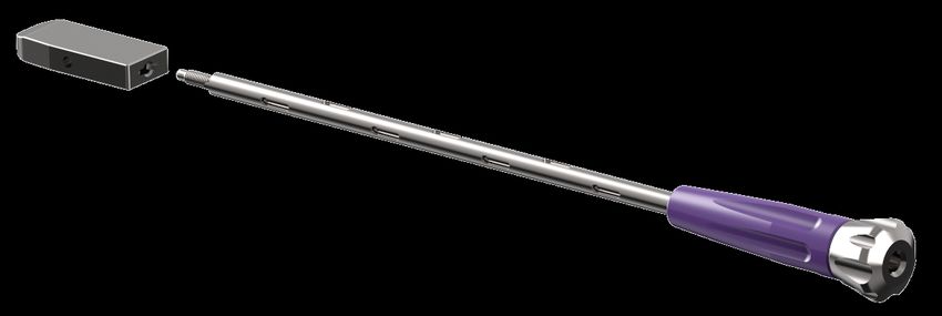
Armado del aro retractor                                                                                                                                   Paso 05
 Assembly of retractor ring                                                                                                                                           Step 05

Para aumentar la estabilidad del aro retractor, pueden conectarse anclajes intradiscales sobre la valva anterior al disco
intervertebral a trabajar (shim tipo cuchilla y shim con fijación de clavija) deslizándolos por los surcos de la valva. Para ello se
consta de un impactor de cuchillas shim (previo montaje de la misma). Una vez impactadas se desacopla del mismo y se
retira el impactor.

To improve stability of the retractor ring, intradiscal anchors can be connected on the anterior blade to the intervertebral disc to work on (blade type shim and shim with clamp),
sliding them on the blade grooves. A shim blade impactor is used (which has been previously mounted). Once impacted, the impactor is disassembled and removed.

                                                                                                                   Desacople de colocador y shim
                                                                                                                         Inserter and shim disassembly

                                                                                                                                                                     Extracción
     Montaje de shim tipo cuchilla                                                                                                                                     Removal
           Blade type shim assembly

                                                          Colocar en surcos de valvas
                                                                 Insert in blade grooves

El sistema de iluminación se une a las valvas del retractor
colocando los extremos del cable de fibra óptica en las
puntas de metal que sirven de guía para la fuente de luz (con
agujeros en la parte superior) luego insertelo en el extremo
superior de los surcos de las valvas hasta que quede fijo.
Conecte la fuente al extremo del cable de fibra óptica.
Encienda la fuente de luz.

The light set is connected to the retractor blades by attaching the tips of the optical
fiber cable to the metal tips that act as a guide for the light source (with holes in the
upper section). Then the light set is inserted in the upper section of the blade grooves
until it is in place. Connect the source to the tip of the optical fiber cable. Turn on the
light source.

 PAG. 07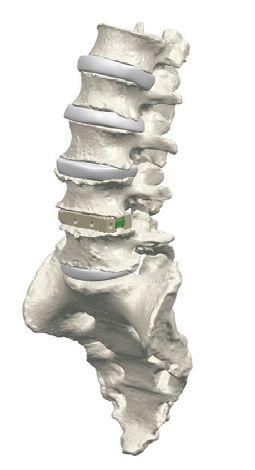
Discectomía y preparación de platillos vertebrales                                                                                                                                             Paso 06
Discectomy and preparation of vertebral endplates                                                                                                                                                           Step 06

Identifique el disco deseado, realice el abordaje y usando un bisturí, comience la discectomía.
La decisión definitiva del implante a utilizar se realizará durante la intervención, tras insertar el implante de prueba.
Identify the target disc and start disc resection using a scalpel.
The final decision about the implant to be used will be made throughout the surgery, after inserting the implant trial.

Nota                    CAJA INTERSOMÁTICA: Implantes radiolúcidos para fusión intersomática elaborados en PEEK (Poliéter étercetona), un
Note                    polímero con excelentes propiedades mecánicas y de biocompatibilidad. Poseen marcadores radiográficos metálicos para
                        ubicar su posición mediante rayos X. Las superficies superior e inferior son dentadas para mejorar la fijación ósea. La fijación
                        se concreta con el acople de placas de TITANIO ASTM F136 (TI°5).
                        INTERSOMATIC CAGE: Radiolucent implants for intersomatic fusion made of PEEK (polyether ether ketone), which is a polymer with excellent mechanical and biocompatibility
                        properties. They have metal radiographic markers to indicate their position using X-rays. The upper and lower surfaces are toothed to improve bone fixation. Fixation is achieved
                        once TITANIUM ASTM F136 (TTI°5) plates have been attached.

Observación             No es necesario eliminar todo el tejido del disco anular posterior. Es suficiente eliminar el espacio correspondiente a la caja
Comment                 intersomática. El mantenimiento de las capas anulares y el ligamento anterior optimiza la estabilidad de la caja y facilita la
                        artrodesis.
                        It is not necessary to sweep away all the posterior annular disc tissue. It is sufficient to remove the space corresponding to the cage. Maintaining the annular layers and the
                        anterior ligament improves cage stability and facilitates the arthrodesis.

PAG. 08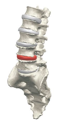
Discectomía y preparación de platillos vertebrales                                                                                                                                        Paso 06
Discectomy and preparation of vertebral endplates                                                                                                                                                  Step 06

Complete la discectomía del disco utilizando los instrumentos requeridos.
Complete the disc discectomy with the following tools.

Nota                   Elimine el material discal del espacio intervertebral con cualquiera de los siguientes instrumentos: periostótomo, curetas
Note                   anulares o de cucharilla, pinzas discales o escariadores. Cuando haya completado la discectomía, sírvase del raspador para
                       resectar las capas cartilaginosas superficiales de los platillos vertebrales, hasta exponer hueso hemorrágico.
                       Remove any remaining disc material from the intervertebral space using the following tools: periosteal elevator, ring or spoon curettes, disc clamps or reamers. Once the
                       discectomy has been completed, use the rasp to resect the surface cartilaginous layers of the vertebral endplates, until the hemorrhagic bone is exposed.

Instrumentales para discectomía X-lock:
X-lock discectomy tools:

PAG. 09
Discectomía y preparación de platillos vertebrales Paso 06 Discectomy and preparation of vertebral endplates Step 06 Finalice la discectomía del disco utilizando las pinzas necesarias. Complete the disc discectomy with the following tools. Pinzas a utilizar: Tools to be used: PAG. 10
Selección de implante de prueba Paso 07
Selection of implant trial Step 07
La selección apropiada del implante se realiza utilizando los probadores de implantes y los implantes de prueba.
Se clasifican por longitud, ancho, alto y lordosis para acomodar la variación en la anatomía del paciente.
The implant is properly selected using paddle distractors and trials.
Implant trials are classified according to length, width, height and lordosis to approximate patient’s anatomical variation.
ÁNGULO DE LORDOSIS
LORDOTIC ANGLE
ALTURA
HEIGHT
LARGO 45
LENGTH 45
LARGO 50
LENGTH 50
LARGO 55
LENGTH 55
PROFUNIDAD 17MM PROFUNIDAD 22MM
DEPTH 17MM DEPTH 22MM
LARGO
LENGTH
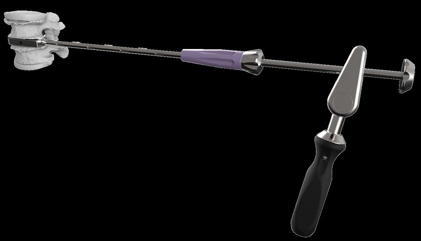
PAG. 11Selección de implante de prueba Paso 07
Selection of implant trial Step 07
Inserte el probador de implante adecuado en el espacio intervertebral utilizando la maza ranurada.
Insert the proper paddle distractor in the intervertebral space with the slotted mallet.
Nota I Durante la fluoroscopia, el mango puede ser
Note I desacoplado para mejorar la visualización.
Throughout the fluoroscopy, the handle can be removed to improve
visualization.
Nota II Los agujeros pasantes en el probador de implantes
Note II son utilizados para determinar la longitud apropiada
del implante.
The through holes of the paddle distractors are used to determine the
proper length of the implant.
Posición Común bajo fluoroscopia:
Standard position under fluoroscopy:
Una vez que se determina el tamaño
adecuado, se pasa a colocar en el espacio
intervertebral el implante de prueba
correspondiente.
Once the proper size has been found, insert the relevant
implant trial in the intervertebral space.
Nota El probador de implantes se puede extraer con la maza ranurada
Note guiándolo a lo largo del eje del probador. La maza reduce al mínimo
la fuerza necesaria para extraer los implantes de prueba y
probadores. Maza ranurada
The paddle distractor can be removed guiding it along the paddle distractor shaft. The mallet Slotted mallet
minimizes the strength required to remove the trials and the paddle distractors.
PAG. 12Selección de implante de prueba Paso 07
Selection of implant trial Step 07
Observación Elegir el implante de prueba correcto es crucial.
Comment It is essential to select the proper implant trial.
La cobertura anteroposterior y lateral del implante en la vertebra debe ser óptimo para proporcionar la mejor posición y
estabilidad posibles de la caja intersomática.
En la vista de anteroposterior, el probador de implante debe asentarse en el anillo periférico del hueso cortical denso.
La caja intersomática puede sobresalir contralateralmente según la preferencia del cirujano.
It is essential to select the proper paddle distractor.
The antero-posterior and lateral coverage of the implant trial on the vertebral endplate must be optimal in order to provide the best possible position and stability of the cage.
In the antero-posterior view, the paddle distractor should seat on the peripheral ring of the dense cortical bone.
The intersomatic cage may protrude contralaterally per surgeon preference.
La lordosis, así como las alturas anterior y posterior se deben elegir para obtener una altura similar a los discos adyacentes,
así como la corrección y el equilibrio sagital para el paciente.
The lordosis, as well as the anterior and posterior heights must be taken into account to reach a height similar to the height of adjacent discs. Also consider the correction to be
made and the sagittal balance for the patient.
Ejemplo: una prueba de implante a 0 ° no En este ejemplo, la prueba de implante 0° ha sido
proporciona la prueba adecuada para el contacto reemplazada por una prueba de 6°: AJUSTE
con la placa vertebral. AJUSTE ANTERIOR ANTERIOR CORRECTO
INADECUADO In this example, the 0°implant trial has been replaced by a 6° implant trial.
CORRECT ANTERIOR ADJUSTMENT
Example: A 0° implant trial does not give enough evidence of the contact
with the vertebral endplate. INADEQUATE ANTERIOR ADJUSTMENT
PAG. 13Selección de implante de prueba Paso 07
Selection of implant trial Step 07
Las selecciones adecuadas de implantes se realizan con implante de prueba. Ellos varian de tamaño por profundidad, altura
y lordosis para acomodar la variación en anatomía del paciente.
Elija el implante de prueba que restablecerá la altura del disco deseada y lordosis, y cárguela en el soporte del implante de
prueba.
Implants are properly selected using implant trials. Implant trials are available in a variety of depths, lengths and lordosis to approximate patient’s anatomical variation.
Select the implant trial to restore the desired height and lordosis of the disc and load it into the implant trial holder.
ÁNGULO DE LORDOSIS PROFUNIDAD ALTURA
LORDOTIC ANGLE DEPTH HEIGHT
LARGO
LENGTH
Nota Introduzca el implante de prueba en el espacio intervertebral. Con ayuda del intensificador de imágenes y mediante
Note palpación compruebe que queda bien encajado. Si quedara demasiado suelto, proceda a probar con el tamaño siguiente.
El implante definitivo deberá tener el tamaño correspondiente al implante de prueba utilizado.
Insert the implant trial in the intervertebral space. The image intensifier and palpation will allow you to ensure proper seating of the implant trial. If the implant trial is loose,
move up to the following size. The final implant should have the size of the implant trial used.
PAG. 14Selección de implante de prueba Paso 07
Selection of implant trial Step 07
Inserte el implante de prueba elegido en el espacio intervertebral
utilizando la maza ranurada. Asegurarse de que sea estable
(compresión leve) entre los cuerpos vertebrales.
Control bajo fluoroscopia:
- Vista lateral: profundidad, posicionamiento anteroposterior y posición
en rotación.
- Vista frontal: centrado, cobertura lateral y posición en rotación.
Insert the selected implant trial in the intervertebral space using the slotted mallet.
Make sure it is stable (gentle compression) between the vertebral endplates.
Control under fluoroscopy:
‐ Lateral view: depth, anteroposterior and rotational positioning.
‐ Front view: centered, lateral view and rotational positioning.
Observación Durante la fluoroscopia, el portaimplantes de prueba puede
Comment ser retirado para una mejor visualización.
Throughout the fluoroscopy, the implant holder can be removed to improve
visualization.
- Los orificios pasantes del implante de prueba permiten la verificación
de la rotación.
‐ The through holes in the implant trial allow to verify rotation.
Una vez que se determina el tamaño adecuado, el implante de prueba
se retira del espacio intervertebral, y la caja intersomática
correspondiente puede ser implantada.
Once the proper size has been determined, the implant trial is removed from the intervertebral space
and the corresponding intersomatic cage may be implanted.
Observación Los implantes de prueba se pueden quitar con la maza
Comment ranurada guiada a lo largo de la varilla de extracción
roscada en el mango colocador de implantes de prueba.
Implant trials can be removed with the slotted mallet guided along the removal
rod threaded in the implant trial inserter handle.
PAG. 15Selección de implante de prueba Paso 07
Selection of implant trial Step 07
Observación Elegir el implante de prueba correcto es crucial.
Comment It is essential to select the proper implant trial.
Introduzca el implante de prueba, con la orientación correcta, en el espacio intervertebral. Todos los implantes lordóticos de
prueba llevan grabadas marcas anteriores y posteriores. En ocasiones puede ser necesario golpear de forma suave y
controlada con la maza sobre el mango para que el implante de prueba quede introducido en el espacio intervertebral.
Insert the implant trial, with the correct orientation, in the intervertebral space.
All lordotic implant trials have anterior and posterior markings on their surface. Sometimes it is necessary to tap the handle gently and in a controlled fashion with the mallet so that
the implant trial is completely inserted into the intervertebral space.
La lordosis, así como las alturas anterior y posterior deben elegirse de modo que se obtenga una altura similar a la del disco
adyacente, así como también para corregir el equilibrio sagital del paciente.
Asegúrese de que las caras superior e inferior del implante de prueba coincidan tanto como sea posible con las placas
terminales vertebrales.
The lordosis, as well as the anterior and posterior heights must be taken into account to reach a height similar to the height of adjacent discs. Also consider the correction to be
made and the sagittal balance for the patient.
Make sure that the upper and lower layers of the implant trial match with the terminal endplates, as much as possible.
Ejemplo: una prueba de implante a 0° no En este ejemplo, la prueba de implante 0° ha sido
proporciona la prueba adecuada para el contacto reemplazada por una prueba de 6°: AJUSTE
con la placa vertebral. AJUSTE ANTERIOR ANTERIOR CORRECTO
INADECUADO In this example, the 0°implant trial has been replaced by a 6° implant trial.
CORRECT ANTERIOR ADJUSTMENT
Example: A 0° implant trial does not give enough evidence of the contact
with the vertebral endplate. INADEQUATE ANTERIOR ADJUSTMENT
PAG. 16Armado del colocador de implante y carga de la caja Paso 08
intersomática Step 08
Assembly of implant inserter and loading of intersomatic cage
Inserte el mango desmontable en el colocador de implante hasta que estos queden
acoplados (para su desacople solo es necesario apretar el botón del mango
desmontable).
Insert the removable handle in the implant inserter until it is fully attached (to remove it, only press the button in the
removable handle).
Eje roscado para bloqueo de implante
Threaded shaft to block the implant
Colocador de implante
Implant inserter
Mango desmontable
Removable handle
Introduzca la varilla roscada a través del colocador y dejela lista para el roscado en el
implante.
Insert the threaded rod through the inserter and leave it ready for threading in the implant.
PAG. 17Armado del colocador de implante y carga de la caja Paso 08
intersomática Step 08
Assembly of implant inserter and loading of intersomatic cage
Tome el implante seleccionado e introduzcalo en el colocador.
Acoplar el gancho del colocador en la ranura situada en el lado posterior de la caja.
Take the implant and insert it in the inserter.
Attach the hook of the inserter into the slot located on the back side of the box.
Atornille la varilla roscada para solidarizar y asegurar la caja en el colocador.
Screw the threaded rod to secure the cage to the inserter.
Importante Asegúrese de que la roseta de la varilla roscada esté alineada con la ranura del mango
Important notice desmontable, para que el impactador pueda ser introducido.
Make sure the clamp is aligned with the groove of the removable handle so that the impactor may be inserted.
PAG. 18Preparación de la caja intersomática Paso 09
Preparation of intersomatic cage. Step 09
La cámara de la caja debe llenarse con sustituto óseo.
The hole of the box must be filled with bone graft.
Nota Relleno del implante con el injerto óseo: Es
Note importante rellenar el implante hasta que el injerto
sobresalga desde las perforaciones de la caja, para
asegurar un contacto óptimo con las placas terminales
de las vértebras.
Filling the implant with bone graft: It is important to fill the implant until the
graft protrudes through the cage holes to secure full contact with the
vertebral endplates.
Compacte la cámara de injerto óseo con el
compactador de injertos.
Compact the bone graft into the chamber using the graft
compactor.
PAG. 19Inserción de la caja Paso 10
Cage insertion Step 10
Inserte la caja en el espacio intervertebral por medio de una ligera presión y de ser necesario por impactos sucesivos en el
colocador de implantes a lo largo del eje lateral (de ser posible evite el impacto).
Insert the cage in the intervertebral space pressing gently and tapping successively on the implant inserter, along the lateral shaft. (If possible, try to avoid tapping).
L: XXXX
POSTERIOR L: XXXX
POSTERIOR
12 X 17 L50 0° 12 X 17 L50 0°
Importante La cara posterior de la caja intersomática ha sido etiquetada.
Important The posterior side of the intersomatic cage has been labeled.
El tope vertebral ajustable se puede agregar al colocador para controlar la posición de la caja durante la inserción.
The adjustable vertebral stop may be added to the inserter to control the position of the cage throughout insertion.
La posición del tope ajustable se puede cambiar intraoperatoriamente con el ajuste del atornillador.
The position of the adjustable stop may be changed intraoperatively by adjusting it with the screwdriver.
Tope vertebral
Vertebral Stop
Importante Asegúrese de que la parada esté configurada en 0 en el comienzo de la colocación.
Important Make sure the stop is set at 0 at the beginning of the insertion.
Atornillador de parada ajustable
Asjustable stop screwdriver
POSTERIOR
POSTERIOR
Observación El tope ajustable permite un posicionamiento milimétrico del implante (con dos vueltas se avanzará 1mm ) y lo mantiene
Comment durante la inserción de la placa de anclaje.
The adjustable stop enables a millimetric positioning of the implant (it moves up 1mm with two runs) and maintains it throughout the insertion of the anchoring plate.
PAG. 20Inserción de la caja Paso 10
Cage insertion Step 10
Confirme la colocación correcta del implante usando fluoroscopia.
Check that the implant has been properly placed with fluoroscopy.
Nota Tres marcadores radiopacos
Note Visualización radiológica de la posición del implante. El marcador lateral está situado
a unos 2 mm del borde del implante. Los marcadores anterior y posterior están
situados a 1,5 mm de los bordes del implante.
Three radiopaque markers
X-ray visualization of implant position. The lateral marker is placed 2 mm away from the implant edge. Anterior and
posterior markers are placed 1.5mm away from the implant edges.
VISTA LATERAL VISTA FRONTAL
LATERAL VIEW FRONTAL VIEW
VISTA LATERAL VISTA FRONTAL
La cara posterior del soporte de la caja corresponde a la cara Los marcadores centrales 1 y 2 indican el implante centro (su
posterior de la caja, permitiendo la visualización del marcador alineación demuestra la ausencia de rotación). El marcador lateral
central de la caja. n°3 indica el recubrimiento lateral (aspecto distal) de la caja.
LATERAL VIEW FRONTAL VIEW
The posterior face of the cage corresponds to the posterior side of the cage, allowing Central markers 1 and 2 indicate the implant center (their alignment shows absence of rotation).
visualization of the central marker of the cage. Lateral marker No. 3 indicates lateral cover (distal aspect) of the cage.
PAG. 21Inserción de la placa de anclaje Paso 11
Insertion of anchoring plate Step 11
Una vez que la posición de la caja intersomática es óptima, se puede insertar la placa
de anclaje para fijar el implante. El impacto de las placas de anclaje se realiza de forma
uniforme, ambas de un solo golpe.
El anclaje debe estar previamente montado en un dispositivo de armado, posicionado
como lo indica su grabado. Inserte el impactor en estado abierto en el dispositivo y
empuje hasta la toma del anclaje, una vez cerrado, rosque la tuerca para fijar el agarre.
Retire el impactor y proceda al armado con el mango del colocador de la caja.
Impactor extractor
Once the intersomatic cage reaches an optimal position, the anchoring plate may be inserted to secure the implant.
Remover extractor
Anchoring plates are impacted consistently, both with only one tap.
The anchor should be previously attached to an assembly device, placed as shown in the markings. Insert the open
impactor in the device and push to reach the anchor. Once it is closed, thread the screw to secure it. Remove the impactor
and assemble with the handle of the cage inserter.
Dispositivo armado de anclaje
Anchorting device assembled
Impactor en estado abierto
Open impactor
Impactor cerrado con placa de anclaje
Closed impactor with anchoring plante
PAG. 22Inserción de la placa de anclaje Paso 11
Insertion of anchoring plate Step 11
Inserte el impactor (previamente acoplado al anclaje) en el colocador. Una vez hermanados deslizar este a lo largo de su guía
hasta hacer tope con la caja intersomática. Golpear sobre el impactor con la maza ranurada, hasta que alcance su tope
mecánico y las marcas grabadas en ambos estén alineadas.
Insert the impactor (which was previously attached to the anchor) in the inserter. Once they are attached, slide the inserter along the guide until reaching the stop with the
intersomatic cage. Tap the impactor with the slotted mallet, until the mechanical stop is reached and the markings of the impactor and the slotted mallet are aligned.
Verifique la colocación correcta de la placa de anclaje usando
fluoroscopia.
Confirm that the anchoring plate has been correctly placed using fluoroscopy.
Tope mecánico
Mechanical Stop
Marcas de impacto alineadas
Aligned impact markings
PAG. 23Control final y desarme del colocador Paso 12
Final checkup and inserter disassembly Step 12
Desenrosque la tuerca del Impactor (de ser necesario utilice la rueda para extracción), esto abrirá las pinzas y se liberarán del
anclaje.
Una vez abierta, retire el Impactor y desacoplelo del colocador.
Unscrew the impactor screw (if required, use the thumbwheel). The clamps will open and the anchor will be released.
Once it is open, remove the impactor and disengage the inserter.
Abierto
Open
Usar solamente para remover
Use only to remove
Desatornille la varilla para liberar el implante del eje roscado del colocador.
Unscrew the rod to release the implant from the inserter threaded shaft.
Desacople el gancho del colocador del surco del implante, mediante una ligera traslación lateral y retírelo cuidadosamente a
lo largo del conducto de abordaje lateral.
Disengage the inserter hook from the implant groove with a slight posterior translation movement and remove it carefully using the lateral approach.
PAG. 24Extracción del implante Extracción
Implant removal Removal
Para retirar el implante se procede de forma análoga a su colocación y con el mismo instrumental con el que fue colocado.
En una primera instancia será necesario tomar la caja intersomática con el colocador.
Acople el gancho del colocador en la ranura que se encuentra en el lado posterior del implante.
To remove the implant use the same procedure that was used for insertion, with the same tools.
First take the intersomatic cage with the inserter.
Attach the inserter hook in the groove in the posterior side of the implant.
Gancho
Hook
Atornille la varilla roscada para asegurar la toma del implante en el colocador.
Screw the threaded rod the implant to the inserter.
PAG. 25Extracción del implante Extracción
Implant removal Removal
Luego de haber enganchado la caja intersomática de peek, acoplar la barra extractora en posición abierta.
After hooking the Peek intersomatic cage, attach the remover rod in open position.
Abierto
Open
Ensamblar la barra extractora abierta en el colocador de implante y empujar hasta su tope mecánico (ambas barras también
cuentan con marcas de posicionamiento) una vez llegado a tope, roscar la tuerca hasta enganchar la placa de anclaje.
Attach the open remover rod to the implant inserter and push it until the mechanical stop is reached (both rods should have positioning markings), then screw until engaging the
anchoring plate.
Abierto
Open
Cerrado
Close
PAG. 26Extracción del implante Extracción Implant removal Removal Verificar que se haya tomado la placa de anclaje de forma correcta, luego se procede a roscar la varilla de extracción. Con la maza ranurada impactar de forma ascendente para comenzar la extracción de la flaca de anclaje de titanio. Confirm that the anchoring plate has been properly seized, and then screw the remover rod. With the slotted mallet, impact upwards so as to begin removing the titanium anchoring plate. Aquí se muestra como se procede a realizar la extracción This shows how to proceed with the removal. Posteriormente se extraerá la caja intersomática de Peek (de ser necesario el colocador puede impactarse para realizar la extracción, tal como se muestra en la imagen) Then remove the Peek intersomatic cage. (If required, the inserter may be impacted for removal, as shown in the picture). PAG. 27
Productos autorizados por la ANMAT PM 2022-12
    Medical device authorized by ANMAT PM-2022-12

                    DC-077-00
También puede leer