MD-5060e Guía del Usuario - Megóhmetro digital
←
→
Transcripción del contenido de la página
Si su navegador no muestra la página correctamente, lea el contenido de la página a continuación
MD-5060e
Megóhmetro digital

Guía del Usuario

                         GU-1045

                     3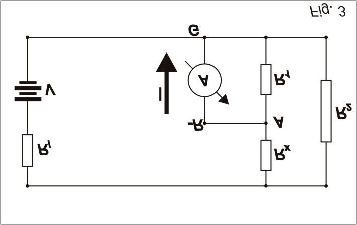
Precauciones de seguridad
En los ensayos que se realizan utilizando este megóhmetro hay involucradas tensiones peligrosas. Si bien la corriente de
salida del megóhmetro está limitada, las capacidades exteriores se cargan a potenciales muy elevados y no hay protección
respecto de ellas, razón por lo cual pueden producir una descarga que puede llegar a ser fatal si no se aplicaran rigurosa-
mente las normas de seguridad pertinentes.

Para la utilización segura del MD-5060e es fundamental que las personas que lo utilicen, sigan las instrucciones y adverten-
cias indicadas en este manual, así como todas las medidas de seguridad habituales.

Estos equipos deben ser operados únicamente por personas calificadas.

                                                             4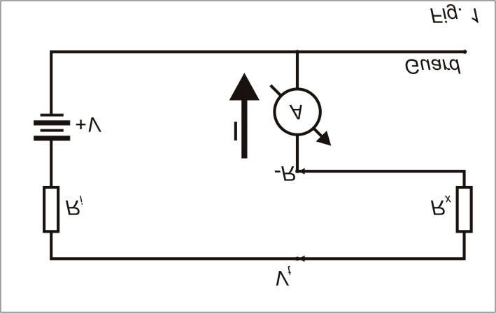
Índice
Precauciones de seguridad ______________________________________________________ 4
Descripción ______________________________________________________________ 6
Instrucciones de Uso _________________________________________________________ 6
    Función de los controles del panel _______________________________________________ 6
    Teclado ______________________________________________________________ 7
    Indicadores luminosos (led’s) __________________________________________________ 7
Indicadores ______________________________________________________________ 7
    Display _______________________________________________________________ 7
    Escala analógica de barras (bar-graph) _____________________________________________ 8
    Indicador luminoso de alta tensión _______________________________________________ 8
    Cronómetro incorporado _____________________________________________________ 8
    Número del ensayo realizado __________________________________________________ 8
Funciones especiales _________________________________________________________ 8
    Selección de tensión (V TEST) __________________________________________________ 8
    Tensiones predeterminadas ___________________________________________________ 8
    Disminuir / Aumentar tensión de ensayo ____________________________________________ 8
    Timer________________________________________________________________ 8
    Voltímetro _____________________________________________________________ 8
    Límite (LIM) ____________________________________________________________ 9
    Memoria (HOLD) _________________________________________________________ 9
    Filtro (FILTER) ___________________________________________________________ 9
    Índice de absorción dieléctrica (DAI) _______________________________________________ 9
    Índice de polarización (PI) ____________________________________________________ 9
    Verificación del estado de la batería _______________________________________________ 9
    Función Impresora (opcional)___________________________________________________10
    Auto-apagado ___________________________________________________________10
Instrucciones de uso paso a paso__________________________________________________10
Transfiriendo datos para la computadora ______________________________________________12
    Puerta de comunicación RS-232 ________________________________________________12
    Conexiones ____________________________________________________________12
    Dentro de su PC _________________________________________________________13
Impresora (opcional) _________________________________________________________15
    Ejemplo de impresión ______________________________________________________15
    Alimentación del papel ______________________________________________________15
    Papel________________________________________________________________15
Cargador de batería__________________________________________________________15
    Carga de la batería:________________________________________________________15
Especificaciones técnicas _______________________________________________________16
Accesorios incluidos__________________________________________________________17
Boletín técnico N° 32 ________________________________________________________18

                                             5
Descripción
El megóhmetro digital inteligente CIRCUTOR modelo MD-5060e, es un equipo de gran versatilidad, robusto y fácil de utilizar.
Emplea una tecnología de probada eficacia, que proporciona mediciones confiables, seguras y precisas de resistencias de
aislación de hasta 5.000.000 MΩ @ 5 kV, con 4 tensiones de prueba preseleccionadas: 500 V – 1 kV - 2,5 kV – 5 kV,
con posibilidad de aumentar o disminuir estos valores en pasos de 500 V.
El microprocesador empleado facilita la operación del equipo y permite la incorporación de funciones tales como cronómetro,
selección automática de rango, memoria, medición de la tensión de prueba, indicación automática de los índices de polariza-
ción (PI - Polarization Index) y absorción dieléctrica (DAI - Dielectric Absorption Index), etc.
Otras características destacadas de este megóhmetro son las tensiones negativas en referencia al borne de potencial cero
(R), para detectar humedad en las instalaciones. Por su tamaño y peso reducidos, autonomía de alimentación y robustez me-
cánica, este equipo es ideal para el uso en trabajos de campo, en condiciones ambientales rigurosas. Es muy simple de
operar y resistente a las severas condiciones de trato que, inevitablemente, incluyen golpes frecuentes, muy altas y bajas
temperaturas, vibraciones intensas durante el transporte por malos caminos, prolongada exposición a la radiación solar
directa, salpicaduras de agua, arena y otras partículas arrastradas por el viento, etc. Todo ello, sin desmedro de la exactitud,
comparable con la de los mejores megóhmetros de laboratorio.
Instrucciones de Uso
Función de los controles del panel
!- Borne de SALIDA DE TENSIÓN (-V) %- TECLADO
"- Borne de REFERENCIA CERO (+R) &- Puerta de comunicación RS-232
#- Borne GUARD (G) '- ENTRADA DE LA FUENTE DE ALIMENTACIÓN
$- DISPLAY (- Control de ALIMENTACIÓN DEL PAPEL
6Teclado Indicadores luminosos (led’s)
)- FILTRO. Oprimida elimina interferencias de ruido - Indica tecla LÍMITE oprimida.
tensiones de prueba. ?- Indica que el CARGADOR DE BATERÍA está actuando.
+- VOLTÍMETRO. Acciona la función voltímetro. @- Indica tecla TIMER oprimida.
,- LÍMITE. Acciona la función límite. A- Indica tecla HOLD oprimida.
-- ESTADO DE LA BATERÍA. Exibe en el display el B- Indica tecla IMPRESORA oprimida
estado de carga de la batería. C- Indica la presencia de ALTA TENSIÓN en el borne de
.- TIMER. Limita el ensayo a 1 minuto de duración. salida. En este momento se deben aumentar los cui-
/- HOLD. Congela en el display la última lectura hecha. dados con la seguridad.
0- Enciende/Apaga la función IMPRESORA D- Indica que la tensión seleccionada es 500V
1- Llave de ENCENDIDO E- Indica que la tensión seleccionada es 1kV
2- Tensión de prueba de 500V F- Indica que la tensión seleccionada es 2,5kV
3- Tensión de prueba de 1kV G- Indica que la tensión seleccionada es 5kV
4- Tensión de prueba de 2,5kV H- Indica tecla START oprimida.
5- Tensión de prueba de 5kV
6- DISMINUYE. Disminuye la tensión en pasos de 500V.
7- AUMENTA. Aumenta la tensión en pasos de 500V.
8- START. Inicio del ensayo
9- PI. Índice de Polarización.
:- STOP. Fin del ensayo
;- DAI. Índice de Absorción Dieléctrica.
Indicadores
Display
Display alfanumérico LCD donde es exibido el resultado de la medición la unidad correspondiente, el tiempo transcurrido
desde el inicio de la medición, el n° de ensayo, la tensión de ensayo seleccionada, la indicación analógica por bar-graph y
mensajes al operador. (en inglés).
mensajens al operador
n° de ensayo tiempo transcurrido
resultado de la medición
unidad correspondiente
indicación analógica tensión de ensayo seleccionada
(bar-graph) mensajens al operador
7Escala analógica de barras (bar-graph)
El equipo indica analógicamente el valor de la resistencia que se está midiendo. En el ejemplo anterior, el display está
indicando 60% del máximo valor de escala. El bar-graph proporciona una visualización de la variación gradual del valor de la
resistencia de aislación durante el transcurso del ensayo.
Indicador luminoso de alta tensión
Un indicador luminoso señala la presencia de alta tensión en el borne de salida durante la medición y continúa encendido
hasta que el proceso de descarga se haya completado.
Cronómetro incorporado
Posee indicación del tiempo transcurrido en minutos y segundos.
Número del ensayo realizado
Indica automáticamente el n° del ensayo que está siendo realizado, lo que permite grabar varios ensayos como documentos
a través de la puerta de comunicación RS-232.
Funciones especiales
Selección de tensión (V TEST)
Función que permite seleccionar la tensión de ensayo a través de las teclas de TENSIONES PRE-DETERMINADAS
(500V-1kV-2,5kV-5kV), u otros valores a través de las teclas de DISMINUIR y AUMENTAR en pasos de 500V.
Cuando esta función esté desactivada, las teclas de tensión quedarán en el modo de seguridad y el equipo no
aceptará ninguna modificación de tensión de ensayo. Cuando el equipo se enciende, ya se inicia con la función V
TEST accionada.
Tensiones predeterminadas
Selecciona tensión de 500V
Selecciona tensión de 1kV
Selecciona tensión de 2,5kV
Selecciona tensión de 5kV
Para utilizarlas es necesario que la función V TEST esté accionada.
Disminuir / Aumentar tensión de ensayo
Aumenta la tensión en pasos de 500V.
Disminuye la tensión en pasos de 500V.
Para utilizarlas es necesario que la función V TEST esté accionada.
Timer
Permite determinar en 1 minuto el fin del ensayo, quedando almacenados en el display todos los valores obtenidos.
Voltímetro
Oprimiendo esta tecla, el equipo medirá la tensión efectivamente aplicada al elemento bajo ensayo.
8Límite (LIM)
Utilizando esta tecla el megóhmetro indicará con un BIP (sonido intermitente) cuando la resistencia de aislación sea
inferior al limite de 100MΩ, actuando en este caso como un dispositivo pasa /no pasa. El led < quedará parpa-
deando hasta terminar el ensayo o hasta que el valor de la resistencia vuelva a superar los 100MΩ.
Memoria (HOLD)
Permite retener en el display la última lectura efectuada en el instante en que se oprimió esta tecla sin interrumpir el
ensayo. Al liberase la tecla, el megóhmetro actualiza el valor medido de resistencia y el cronómetro. El led ? encen-
dido y la letra H en el display, indican que esta función fue activada.
Filtro (FILTER)
Cuando se realizan mediciones en transformadores o en máquinas de grandes dimensiones, en presencia de grandes
campos electromagnéticos, es posible que la lectura del equipo sea inestable, sobretodo para valores de resistencias
mayores que 300MΩ. En estos casos es conveniente presionar la tecla FILTER antes de iniciar la medición. Esta
función permite llegar al valor de resistencia de aislamiento en una curva ascendente sin oscilaciones.
Índice de absorción dieléctrica (DAI)
Realiza el ensayo de Índice de Absorción Dieléctrica automáticamente. En este tipo de ensayo, el megóhmetro debe
quedar encendido, aplicando alta tensión a la muestra, durante 1 minuto (60 segundos). Después de ese tiempo, el
operador debe oprimir la tecla DAI para leer en el display el valor del índice de absorción. Si se anticipa a oprimir la
tecla DAI antes de transcurrido 1 minuto el display indicará DAI = - - - . El Índice de Absorción Dieléctrico es el
cociente entre el valor de la resistencia de aislación medido a los 60 segundos y el valor medido a los 30 segundos y
es útil en el mantenimiento preventivo de bobinados (de transformadores, motores, generadores, etc.).
DAI = R 60 segundos
R 30 segundos
Índice de polarización (PI)
Realiza el ensayo del Índice de Polarización automáticamente. En este tipo de ensayo el megóhmetro debe quedar
encendido, aplicando alta tensión a la muestra, durante 10 minutos. Después de ese tiempo el operador debe apretar
la tecla PI para que el megóhmetro indique en el display el valor del índice de polarización. Si se anticipa a oprimir la
tecla PI antes de transcurrido 10 minutos el display indicará PI = - - - . El índice de polarización es el cociente entre el
valor de la resistencia de aislamiento medido a los 10 minutos y el valor medido a 1 minuto. Este índice es muy útil
en el mantenimiento preventivo y predictivo para detectar la deterioración de la resistencia de aislamiento por la
presencia excesiva de polvo, suciedad, grasas o acción de agentes químicos / físicos, etc.
PI = R 10 minutos
R 1 minuto
Verificación del estado de la batería
Durante la medición es posible verificar el estado de la batería. Para eso se debe mantener oprimida esta tecla y
verificar la indicación en el display. Será indicado BAT. OK si la carga fuera suficiente, o LOW BAT en el caso de que
la batería precise ser recargada. La escala analógica de barras (bar-graph), da una idea aproximada del porcentaje de
carga remaneciente (mínimo de 20% para operación normal).
9Cuando la carga de la batería alcance el valor mínimo de operación normal aparecerá automáticamente el mensaje
LO BAT en el área en que se muestra el valor de la tensión de ensayo, alternándose con la misma a cada 1 segundo.
Función Impresora (opcional)
Para habilitar la función impresora, oprima la tecla 0 antes de iniciar el ensayo. Los valores medidos serán impresos
a cada 15 segundos. El Índice de Absorción Dieléctrica y el Índice de Polarización serán impresos después de 1
minuto y 10 minutos respectivamente. La impresión puede ser iniciada o terminada en cualquier momento durante el
ensayo.
Auto-apagado
La función de auto-apagado, (Auto-Power-off) desactiva el consumo del equipo en dos situaciones:
• Durante una medición – Después de 35 minutos de funcionamiento sin que, durante este período, sea ejecutada la
función de verificación del estado de la batería.
• Equipo ocioso – Después de 10 minutos de inactividad.
Instrucciones de uso paso a paso
1. Asegúrese que no existan diferencias de potencial ELEMENTO A MEDIR
entre los puntos a los cuales se conectará el megóh- TERMINAL
ROJO
metro, ni entre ellos y tierra.
2. Conecte el terminal de seguridad del cable rojo al
borne de salida de tensión –V del megóhmetro.
3. Conecte el terminal BNC del cable negro al borne de TERMINAL
NEGRO
REFERENCIA CERO (+R) y los terminales cocodrilo al
elemento a medir como indica la figura.
BNC
TERMINAL DE
4. Según la medición que se vaya a realizar, puede NEGRO
SEGURIDAD
emplearse o no el borne G (GUARD).
Los terminales cocodrilo en el dibujo son meramente ilustrativos pudiendo haber
diferencias entre éstos y los que verdaderamente acompañan al equipo
dependiendo de las opciones hechas durante la compra de este megóhmetro.
10IMPORTANTE: Durante las mediciones, el megóhmetro debe estar eléctricamente referido a tierra para evitar que el
equipo quede a un potencial elevado lo que provoca lecturas inestables. Cuando se mide aislamiento respecto de tie-
rra, el borne R está conectado a tierra y se cumple la condición de fijar el potencial del equipo. En cambio, cuando la
medición se realiza entre dos puntos que no están conectados a tierra (por ej., entre dos conductores de fase en un
cable trifásico) el borne GUARD del megóhmetro debe conectarse a tierra. Esto implica que siempre que se mide,
uno de los bornes GUARD o R debe estar conectado a tierra, pero no ambos simultáneamente. El Boletín Técnico
N° 32 explica el uso del borne GUARD para eliminar el efecto de resistencias parásitas, cuya influencia sobre la medi-
ción se desea evitar.
1. Encienda el equipo con la llave de encendido 1. En el display aparecerá el siguiente mensaje:
CIRCUTOR MD-5060e y Inmediatamente aparecerá el mensaje: PRESS START
2. Seleccione la tensión de prueba con una de las teclas de tensión predeterminadas del teclado del panel de control. Si
se desea una tensión de prueba intermedia entre estos valores podrá obtenerla oprimiendo las teclas de AUMENTAR
o DISMINUIR en pasos de 500V. Esto permite seleccionar tensiones de 500, 1000, 1500, 2000, 2500, 3000, 3500,
4000, 4500 y 5000Vcc.
3. Después de seleccionar la tensión deseada se puede liberar la tecla V TEST que dejará la tensión seleccionada
programada y entrará en el modo de seguridad.
4. Oprima la tecla START. Inmediatamente el led de ALTA TENSÃO se encenderá indicando que el generador interno
del megóhmetro está aplicando alta tensión al elemento bajo prueba. Si la función V TEST hubiera sido accionada al
comienzo del ensayo, el led = se apagará indicando que la tensión ya fue programada y que el equipo entró auto-
máticamente en el modo de seguridad. Si durante el ensayo fuera necesario el cambio de tensión de prueba, se debe
accionar la función V TEST.
5. Durante algunos segundos el sistema inteligente de auto-rango buscará el rango mas conveniente para el valor que
se está midiendo. En ese tiempo el display mostrará el mensaje: WAIT...
6. Luego el display mostrará el n° do ensayo, el valor de la tensión seleccionada e iniciará el conteo del tiempo transcu-
rrido. Si el valor medido estuviera dentro del alcance del instrumento, la indicación del n° de ensayo dará lugar para la
indicación del valor de la resistencia y su unidad correspondiente, e iniciará la indicación analógica por bar-graph.
7. Si por ejemplo, el valor medido es de 601 MΩ con tensión seleccionada de 1.000 V el display quedará inicialmente
durante algunos segundos, como indicado abajo, informando que fue iniciado el ensayo n° 12.
8. Después de algunos segundos, en el mismo ejemplo, el display indicará que el valor de la resistencia medida es de
601 MΩ, como indicado
119. Si el valor medido sobrepasa 5000 GΩ a 5 kV, el mensaje será:
Transfiriendo datos para la computadora
Puerta de comunicación RS-232
En la puerta de comunicación RS-232 del megóhmetro se puede conectar una impresora con conexión serial, una computa-
dora con software de comunicación, etc.
Velocidad de transferencia: 4800 bps
8 bits - sin paridad 1 stop bit (8,n,1)
Conexiones
Para transferir datos del MD-5060e a una computadora tipo PC, utilice el cable que se provee junto con los accesorios.
Conecte el mismo en la puerta de comunicación RS-232, y el otro extremo al conector RS-232 de su PC.
12Dentro de su PC
Entre en el menú: Iniciar > Programas > Accesorios > Comunicaciones > Hiper Terminal
Meu computador
Meus locais de rede
Windows Explorer
Lixeira
Programas
Documentos softwares
Configurações
Pesquisar
Ajuda
Executar
Desligar
Iniciar 12:00
Descrição da conexão ? X Conectar a ? X
Nova conexão MOTOR
Digite um nome e selecione um ícone para a conexão: Informe os detalhes do número do telefone que deseja discar:
Nome:
MOTOR| País/região: Brasil (55)
Ícone Código da cidade: 011
Direcionar para Com1
OK Cancelar OK Cancelar
Para crear una nueva conexión digite un nombre y seleccione Verifique la existencia de una puerta de comunicación
un icono. En el ejemplo el nombre elegido fue “motor”. accesible por ejemplo Com 1 o Com 2 . Indique en la
Clique en OK ventana siguiente y dé un OK. En este ejemplo la Com 1
13Propriedades de Com1 ? X
4800
8
Nenhum
1
Nenhum
Avançadas Restaurar padrões
OK Cancelar Aplicar
En la ventana siguiente llene los datos: 4800, 8, ningún, 1,
ningún
En este momento la PC está lista para recibir las informaciones de la medición al oprimir la tecla START. El MD-5060e
comenzará a enviar los datos a la computadora.
Las informaciones transmitidas serán las siguientes:
Ensayo N°...; Tiempo [en minutos y segundos]; Tensión de Prueba [en kVolts]; Valor de la resistencia y unidad.
Hyper Terminal X
14Impresora (opcional)
Ejemplo de impresión
Alimentación del papel
La llave (, una tecla azul localizada en la parte superior izquierda del cuerpo de la impresora, es el Control de Alimentación
del Papel. Oprima esta tecla 3 veces después del termino del ensayo y antes de cortar el papel, con la finalidad de visualizar
las últimas lineas. ATENCIÓN: No tire del papel, siempre use la tecla de Alimentación de Papel. Nunca intente introducir el
papel de vuelta para la impresora. En cualquier de estos casos la impresora puede dañarse fácilmente.
Papel
Lado blanco
Esta impresora utiliza papel térmico, 37mm de ancho, en una bobina de hasta 33mm de
diámetro. La figura abajo muestra como colocar el papel. Oprima la tecla ( hasta el
papel aparecer. Para retirar la bobina de papel antigua, corte el papel cerca de la bobina y
oprima la tecla (. Las operaciones de retirada de la bobina usada deben ser efectuadas
de esta manera por que el movimiento del papel es unidireccional, o sea, el papel se
Lado amarillo mueve solamente en una dirección.
Cargador de batería
Este equipo posee incorporado un dispositivo inteligente de última generación que controla la carga de la batería y la
alimentación del equipo desde la red de energía eléctrica.
Carga de la batería:
Para cargar la batería siga el siguiente procedimiento:
1. Verifique que la llave 1 de ENCENDIDO esté en la posición de apagado (OFF).
2. Conecte el equipo a la red de energía eléctrica a través de la fuente de alimentación.
3. Después de algunos segundos el led ? de CARGADOR DE BATERÍA, se encenderá en color rojo, indicando así que el
proceso de carga se há iniciado. Cuando la carga se haya completado la luz del Led cambiará a verde, permaneciendo así
hasta que el equipo sea desconectado del tomacorriente.
Luz verde y roja alternadas Evaluación del estado inicial de la batería al conectar la
fuente, durante un segundo.
Luz roja permanente Batería en carga.
Luz roja intermitente Indica problema de carga de la batería.
Luz verde permanente Carga finalizada con éxito. Batería OK.
15Si durante la carga de la batería el equipo fuera conectado, accionando la llave 1, para efectuar una medición, la carga
quedará temporariamente interrupta. Si el led ? de CARGADOR DE BATERÍA estuviera con luz roja, se apagará y toda la
carga será destinada para alimentar el equipo. Si el led estuviera con luz verde, continuará encendido indicando que la
batería está cargada (pero deja de cargarse). Al terminar la medición, cuando se desconecte el equipo, la carga se reiniciará
automáticamente.
Nota: la batería pierde parte de su carga estando almacenada. Por eso, antes de utilizar el megóhmetro por primera vez, o
después de un cierto tiempo sin uso, se debe cargar la batería.
Especificaciones técnicas
Tensiones de prueba : 500, 1000, 2500, 5000V con selección rápida.
500V a 5kV en pasos de 500V
Tensión continua, negativa respecto de tierra.
Alcance : 5TΩ @ 5 kV
Corriente de cortocircuito : 1,5 ± 0,5mA
Exactitud de las tensiones : ± 3% del valor nominal sobre una resistencia de 10GΩ
de prueba
Exactitud básica del : 5% de la lectura ± 3 dígitos
megóhmetro (1MΩ a 500GΩ en cualquier tensión de prueba)
Características avanzadas : • Cálculo automático del Índice de Polarización
• Cálculo automático del Índice de Absorción Dieléctrica
• Ensayos Pasa / No pasa y de tiempo fijo
Impresora (opcional) : Imprime el tiempo transcurrido, la tensión realmente aplicada a la carga y la resistencia
medida
Salida serial de datos : RS-232 a 4800bps. Permite la conexión con una impresora serial, un computadora portátil o
de mano, o un colector de datos.
Cronómetro incorporado : Muestra el tiempo transcurrido desde el inicio de la medición en formato mm:ss
Índice de protección : IP54 (con la tapa cerrada)
ambiental
Seguridad : Cumple los requerimientos de la norma IEC 61010-1/1990, IEC 61010 1/1992 anexo 2
Compatibilidad electromag- : De acuerdo con IEC 61326-1
nética (E.M.C)
Inmunidad a las radiaciones : De acuerdo con IEC 61000-4-3
electromagnéticas
16Inmunidad electrostática : De acuerdo con IEC 1000-4-2
Alimentación : Batería recargable interna (12 V - 2,3 Ah) o fuente externa de 18 V – 1,2 A
Cargador de batería : 18 V – 1,2 A
Temperatura de operación : -5°C a 50°C
Temperatura de almace- : -25°C a 65°C
namiento
Humedad : 95% RH (sin condensación)
Altura máxima : 3000m sobre el nivel del mar
Peso : Aprox. 3kg
Dimensiones : 274 x 250 x 124mm
Accesorios incluidos
• Cables de medición de 1,80m (2).
• Cables para GUARD de 1,80m.
• Fuente de alimentación.
• Cable para RS-232.
• Manual de operaciones.
17Boletín técnico N° 32
Utilidad del borne “Guard” de los megóhmetros
Cuando se realizan mediciones de resistencias de aislamiento con megóhmetros, especialmente con instrumentos de alta
sensibilidad, que miden resistencias de valor muy alto, resulta conveniente el empleo del borne “Guard”, que permite inde-
pendizar la medida realizada de las resistencias parásitas cuya influencia en la medición se desea evitar.
Para comprender mejor la función de este borne conviene comenzar analizando el esquema básico del megóhmetro.
Donde:
Vt: Generador de tensión de c.c.
Ri: Resistencia interna del generador
A: Nano-amperímetro del microprocesador
La resistencia incógnita (Rx) se conecta entre los bornes ”-V” y “R”. Su valor determina la corriente que circula en el circuito,
que es leída por el circuito de corriente del microprocesador representado en la figura como un nano-amperímetro A. El valor
de Rx puede ser determinado mediante la siguiente ecuación:
En muchos casos, la resistencia que se pretende medir aparece en paralelo con otras resistencias parásitas cuya influencia
en el valor medido debe minimizarse.
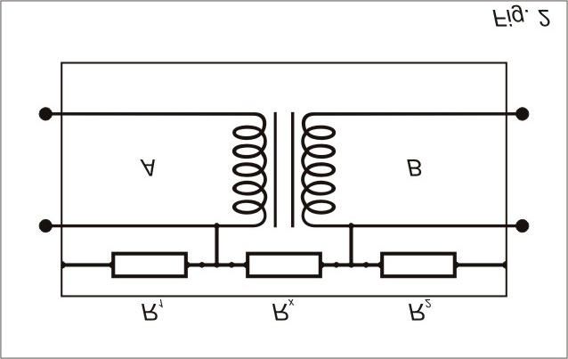
Un ejemplo típico de esta condición es el caso en que se debe medir la resistencia de aislamiento entre primario y secunda-
rio de un transformador montado dentro de una carcaza metálica:
Rx: Resistencia de aislamiento entre primario y secundario.
R1: Resistencia de aislamiento entre primario y carcaza.
R2: Resistencia de aislamiento entre secundario y carcaza.
.
18Si conectamos el megóhmetro (a través de los bornes -V y R) a los terminales A y B del transformador y ya que las resis-
tencias de las espiras de cada lado del transformador son despreciables frente a la de aislamiento entre primario y secunda-
rio, aparecerá para el megóhmetro una resistencia Rx en paralelo con R1 + R2, por lo que el megóhmetro indicará una
resistencia menor que la esperada.
La situación se modifica si conectamos la carcaza del transformador al borne GUARD.
Resulta el siguiente circuito:
En el circuito de la fig. 3 se observa que R1 está en paralelo con una resistencia de bajo valor (la del nano-amperímetro) y
por lo tanto, tiene una influencia despreciable en la lectura.
Por la resistencia R2 circula una corriente que no pasa por el circuito de corriente del microprocesador (nano-amperímetro) y
por lo tanto no afecta la lectura. Haciendo un análisis más detallado se observa que la corriente a través de R2 genera un
pequeño error, ya que produce una caída de tensión adicional en R1, pero que se puede considerar totalmente despreciable,
(especialmente en los megóhmetros digitales)
Para todos los efectos prácticos de utilización del megóhmetro se debe considerar que, si R1 y R2 son mayores que
100MΩ, cualquier valor de Rx será medido con un error despreciable utilizando el borne GUARD del que resultaría de
realizar la lectura sin la utilización del mismo.
Un ejemplo numérico permite cuantificar lo anteriormente expuesto.
Supongamos para la figura 3 los siguientes valores:
Rx = 3.000MΩ
R1 = 100MΩ
R2 = 100MΩ
El valor medido sin utilizar el borne GUARD sería de 187,5MΩ y por lo tanto totalmente inútil.
En cambio, utilizando el borne GUARD conectado a la carcaza, se mide el valor de 3.000MΩ.
19Apuntes
20MD-5060e
Digital insulation tester
User’s guide
21Safety warnings
In the tests carried out using this megohmmeter there are dangerous voltages involved, and so the operator has to be a
properly trained person.
Before connecting the equipment, it has to be verified that the circuit to be submitted to the test is free of voltage. None of
the circuit points can be touched during a test.
Capacitive loads need to be under special care as they are charged at high voltages during the test without any current
limiting device capable to protect the operator in case of accidental contact. On completion of a test these potentials are
discharged slowly. During this decaying time the equipment High Voltage indicator is lighted on. The operator has to pay
attention to this indication, waiting for 15 second after the LED is switched-off in order to safely short-circuit the terminals
with a shorting link before disconnecting the test leads.
When using this equipment, safety regulations applicable to jobs carried out under voltage have to be appropriately followed.
22Index
Safety warnings ____________________________________________________________22
Description_______________________________________________________________24
Operating instructions_________________________________________________________24
Panel control functions ______________________________________________________24
Keyboard _____________________________________________________________25
Led’s ________________________________________________________________25
Indicators _______________________________________________________________25
Display _______________________________________________________________25
Analogue bar-graph. _______________________________________________________26
High voltage light indicator ____________________________________________________26
Built-in chronometer _______________________________________________________26
Test number____________________________________________________________26
Special features ____________________________________________________________26
Voltage selector __________________________________________________________26
Predetermined output voltages__________________________________________________26
Increase and decrease keys ___________________________________________________26
Timer________________________________________________________________26
Voltmeter _____________________________________________________________26
Limit (LIM)_____________________________________________________________26
Memory (HOLD)__________________________________________________________27
Filter ________________________________________________________________27
Dielectric absorption index (DAI) _________________________________________________27
Polarization index (PI) _______________________________________________________27
Battery test ____________________________________________________________27
Function Built-in printer (Optional feature)____________________________________________28
Auto power-off __________________________________________________________28
Operation step by step ________________________________________________________28
Data collection in the computer ___________________________________________________30
RS 232 output port _______________________________________________________30
Transfer data to a computer ___________________________________________________30
Built-in printer (Optional feature) ___________________________________________________33
Printing sample __________________________________________________________33
Paper feed_____________________________________________________________33
Paper _______________________________________________________________33
Battery charger ____________________________________________________________33
Battery Charge: __________________________________________________________33
Technical specifications ________________________________________________________34
Supplied accessories _________________________________________________________35
Application note N° 32 ________________________________________________________36
23Description
The CIRCUTOR model MD-5060e digital electronic ohmmeter is a versatile, robust and easy-to-use equipment. It uses an
efficient well experienced technology, which provides reliable, safe and accurate measurements up to 5,000,000 MΩ @
5 kV, with 4 pre-selected test voltages: 500, 1000, 2500 and 5000 V, and with the possibility to select others test voltages
between 500 and 5000 Vdc in 500 V steps.
Its microprocessor-based development makes the equipment operation easier and enables the introduction of functions such
as auto-range self, memory, test voltage measurement, polarization and absorption Index indication, etc. Other feature that is
important in this megohmmeter is negative voltages that refer to the zero potential terminal (R).
Due to its reduced dimensions and weight, power supply autonomy and mechanical resistance, this equipment is suitable for
fieldwork, and under extreme weather conditions. It is very simple to be operated and resistant to violent treatment, which
unavoidably includes frequent bumps, extremely high or low temperatures, intense vibrations during transportation over rough
roads, long exposure to direct sunlight, dust, sand and other wind-carried particles, etc. Everything without affecting its
accuracy, comparable to the best laboratory instruments.
Operating instructions
Panel control functions
!- NEGATIVE terminal (-V) %- KEYBOARD
"- POSITIVE RETURN terminal (+R) &- RS 232 output
#- GUARD terminal (G) '- POWER SUPPLY INPUT
$- DISPLAY (- PAPER FEED control
24Keyboard Led’s
)- FILTER. Eliminates noise interference. - Indicates LIM key on
instrument is at the voltmeter function. ?- Indicates BATTERY CHECK key on
,- LIM. The instrument indicates with a sound signal. @- Indicates TIMER key on
when R< 100MΩ A- Indicates HOLD key on
-- BATTERY CHECK. B- Indicates PRINT key on
.- TIMER. the test will be stopped automatically after one C- Indicates that the HIGH VOLTAGE is ON the terminals.
minute. In this moment is necessary increase the safety warn-
/- HOLD. When pressed, the instrument displays the last ings.
resistance reading done. D- Indicates that the selected voltage is 500V
0- Enable/Disable the PRINT function E- Indicates that the selected voltage is 1kV
1- ON/OFF key. F- Indicates that the selected voltage is 2,5kV
2- 500V voltage test. G- Indicates that the selected voltage is 5kV
3- 1kV voltage test. H- Indicates START key on
4- 2,5kV voltage test.
5- 5kV voltage test.
6- DECREASE. Decrease test voltages in 500V steps.
7- INCREASE. Increase test voltages in 500V steps.
8- START key.
9- PI. Polarization Index.
:- STOP key.
;- DAI. Dielectric Absorption Index.
Indicators
Display
Alphanumeric LCD where the test number, measurement results, the measuring unit, the time indication (in minutes and
seconds), the analogue indication by means of a bar-graph and messages to the operator are displayed.
messages to the operator
test number time indication
measurement results
measuring unit
analogue indication selected voltage
(bar-graph) messages to the operator
25Analogue bar-graph.
Located on the display lower left part, it analogically indicates the resistance value being measured.
High voltage light indicator
A light indicator displays the occurrence of high voltage on the output terminal during the measurement and keeps lit until the
discharging process has been completed.
Built-in chronometer
It features time indication in minutes and seconds.
Test number
Automatically indicates a number on the display, when the test is started.
Special features
Voltage selector
When * V TEST is pressed, it allows programming testing voltages.
Predetermined output voltages
500V voltage test.
1kV voltage test.
2,5kV voltage test.
5kV voltage test.
To use them it is necessary that function V TEST is actived.
Increase and decrease keys
Increase output voltage in steps of 500V.
Decrease output voltage in steps of 500V.
To use them it is necessary that function V TEST is actived.
Timer
The timer automatically starts when the test button is pressed. Test duration is one minute, when the test will be
stopped automatically.
Voltmeter
By pressing the + key, the instrument will measure the voltage effectively applied to the element being tested.
Limit (LIM)
By pressing , key the megohmmeter works like “pass-fail test" instrument. When the resistance is lesser than
100MΩ the instrument indicates with a sound signal and > / led will be blinking.
26Memory (HOLD)
When / key is pressed the instrument is at the memory function and, therefore, holding the value of the last
performed measurement on the display.
Filter
When are made measurements of transformers or machines of great dimensions, in the presence of great electro-
magnetic fields, is possible that the reading of the equipment be unstable, over all for values of resistance greater
than 300MΩ. In these cases is advisable to press FILTER key before initiating the measurement.
Dielectric absorption index (DAI)
For this kind of tests, the apparatus should be connected, applying high voltage to the sample for 1 minute (60
seconds). After this period, the operator must press the DAI ; key to read the absorption index value on the display.
If this key is pressed before the 1-minute period has elapsed, the display will show DAI = - - -.
DAI = R 60 sec
R 30 sec
The Dielectric Absorption Index is the ratio between the insulation resistance value measured after 60 seconds and
the value measured after 30 seconds. This value is useful to determine whether it is necessary to perform preventive
maintenance on the coils (transformers, engines and motors, generators, etc.).
Polarization index (PI)
For this type of tests, the megger must be connected and apply high voltage to the sample for 10 minutes. After this
period, the operator must press the PI key 9 to display the PI value on the megger display. If the key is pressed
before the 10-minute period has elapsed, the display will show PI= - - -.
The polarization index is the ratio between the insulation resistance value measured after 10 minutes and the value
measured after 1 minute.
PI = R 10 minutes
R 1 minute
The polarization index is useful to determine whether it is necessary to perform preventive maintenance. In addition, it
is useful to detect any insulation resistance wear and tear due to the excess of dust, grease, or else the action of
chemical or physical agents, etc.
Battery test
During the measurement, check if the battery is charged. Press the “BATTERY" key -, and check the display infor-
mation. If the charge is enough, it will read "BAT OK" or “LOW BAT", should it be recharged. The analogue bar-graph
will give an approximate idea of the remaining charge percentage (at least 20% is required for a normal operation).
27Function Built-in printer (Optional feature)
In order to enable the printing function press key 0 before to start the test. Measured values will be printed each 15
seconds, and the Dielectric Absorption Index and Polarization Index will be printed when they becomes ready (after 1
minute and 10 minutes respectively). Printing may be started or stopped at any time during the test.
Auto power-off
After some minutes operation the instrument turns itself off automatically, thanks to its unique "auto-power-off"
system.
Operation step by step
1. Check if there is no differences of potential voltage ELEMENT TO BE MEASURED
between across the points where the megohmmeter RED
CLIP
shall will be connected to, nor between them and the
ground.
2. Connect the red security terminal (red cable) to the
megohmmeter (-V)! terminal.
BLACK
CLIP
3. Connect the black cable to the megohmmeter (+R)"
terminal.
BLACK BNC
CONECTOR RED PIN
4. The green terminal (GUARD) will not be always used.
Application Note #32 explains the usage of Guard ter-
minal for minimising the parasite resistance effect,
whose influence one intends to minimise. If the meas-
urement is performed between two parts, which are not
grounded (for example: a transformer high and low volt-
age windings), the megohmmeter Guard terminal will be
grounded for defining the instrument potential. When-
ever a measurement is performed, the +R or the guard
terminal will be grounded, but not both simultaneously.
If none of these terminals are grounded, the megohm-
meter can be subjected to a higher potential, hazardous
to the operator; and the reading can result unstable and
unreliable. If both terminals are simultaneously
grounded, they will be short-circuited, and the me-
gohmmeter will not perform the measurement.
5. Connect the free ends of the cables in use (red and black jaw connectors) to the element to be measured.
6. Press the ON/OFF1 switch.
7. Initially the display will indicate: CIRCUTOR MD-5060e
8. And then: PRESS START
289. Press key * and select the Voltage Test with any of the 2 to 5 keys. If you want other Voltage Test between
500V and 5kV, press 6 or 7 key.
10. If the key * is pressed again the voltage test selected will be hold, but it is not necessary.
11. Press the START key 8. Shall the "HIGH VOLTAGE" light indicator C will be on, indicating that the megohmmeter
internal generator is applying the selected voltage to the element being tested. The = LED will turn off.
12. For a few seconds, the self-scale smart system will search for the most convenient range for the value being meas-
ured. Meanwhile, the display will show the message "WAIT..." Then, the display will show during a few seconds , the
number of test and then the measurement result using both digital (measurement value and unit) and analog displays.
13. If, for example, the measure value was 601 MΩ with 1.000 V voltage test, it will be read.
14. If the measured value exceeds 5000 GΩ @ 5 kV, it will be read the following message:
29Data collection in the computer
RS 232 output port
Baud rate: 4800 bps
8 bits - non-parity 1 stop bit (8,n,1)
A serial printer, a data collecting device, a communication software equipped PC, etc. can be connected to the megohmmeter
RS232 output port.
Transfer data to a computer
To transfer data from the MD-5060e to a PC-type computer, use the cable provided with the accessories. Connect it to
RS-232 PORT &, and the opposite end of your PC RS-232.
30Open "Start Menu", then go to "Programs", "Accessories", "Communications", until you get to "Hyper Terminal", as shown in
the figure below:
Meu computador
Meus locais de rede
Windows Explorer
Lixeira
Programas
Documentos softwares
Configurações
Pesquisar
Ajuda
Executar
Desligar
Iniciar 12:00
Descrição da conexão ? X Conectar a ? X
Nova conexão MOTOR
Digite um nome e selecione um ícone para a conexão: Informe os detalhes do número do telefone que deseja discar:
Nome:
MOTOR| País/região: Brasil (55)
Ícone Código da cidade: 011
Direcionar para Com1
OK Cancelar OK Cancelar
To set up a new connection, enter a name and then select Then check if there is an accessible communications port, for
an icon. In this example, the name chosen was "MOTOR". instance Com 1 or Com 2. Choose the correct port in the
Click OK. next window. In this example, the port would be Com 1.
31Propriedades de Com1 ? X
4800
8
Nenhum
1
Nenhum
Avançadas Restaurar padrões
OK Cancelar Aplicar
After clicking on OK, go to the next window to fill out the
relevant data 4800, 8, none, 1, none
Now the PC is ready to collect the information obtained from measurements. If START 8 is pressed, the MD-5060e will
start sending data to the computer. A typical line can feature the following format:
Hyper Terminal X
32Built-in printer (Optional feature)
Printing sample
Paper feed
Key (, a blue button located at the upper-left in the printer body, is the Paper Feed control. Press this button for 3 times
after the end of the test and before to cut the paper, in order to advance the paper sufficiently to keep the last lines.
CAUTION: Do not pull the paper, always use the Paper Feed button. Never pull the paper back. The printer could be easily
damaged by pulling the paper in any direction.
Paper
This printer uses a thermal paper, 37mm wide, in a roll of up to 33mm diameter. Figure
below shows how to insert the paper. Press Key ( until paper appears. To change the
paper roll please cut the paper before it enters inside the printer, and then press the
Paper Feed button (, because the paper movement is uni-directional.
Battery charger
This apparatus includes a built-in, state-of-the-art device that controls battery charge and power supplied to the apparatus
from the electric supply network.
Battery Charge:
The equipment has a built-in intelligent circuit that controls the battery charge process. The following process has to be
followed to charge the battery:
• Check if switch 1 is off.
• Connect the power supply cable plug into INPUT'.
• After a few seconds, the red indicator LED ? will turn on until charge is complete. When the green LED turns on, it will
remain lit until the unit is disconnected.
Alternate green and red lights Evaluation of the battery initial status when the source is connected,
during one second.
Steady red light Battery under charge.
Flashing red light The battery was not successfully charged. It denotes some trouble in the
battery charging process.
Steady green light The charge has successfully finished. The battery is OK.
33If, during this battery charge process the equipment is connected to start measurements, the charge process will be tempo-
rarily interrupted. If the red LED ? is lit, it will turn off and all the charge will be used to feed the equipment. If the green
LED ? is on, it will remain lit to show the battery is charged (though it ceases to charge it). Upon completing measure-
ments or when the apparatus is disconnected, the charge process will automatically resume.
Note: The battery looses part of its charge when stored. Therefore, the battery should be recharged before using the megger
for the first time or after a given period without being used.
Technical specifications
Test voltages (T.V.) : 500, 1000, 2500, 5000 V directly, one button selectable.
500 V to 5 kV in 500 V steps.
DC, negative.
Maximum resistance : 5TΩ @ 5 kV
reading
Short circuit current : 1,5 ± 0,5mA
Test voltages accuracy : ± 3% of nominal test voltages on R ≥ 10GΩ
Megohmmeter basic : ± 5% of reading ± 3 digits
accuracy (1MΩ to 500GΩ at any test voltage)
Advanced features : • Automated Polarization Index computing
• Automated Dielectric Absorption Ratio computing
• Pass fail test
Built-in printer : Prints elapsed time, actual voltage and resistance measured.
Serial data output : RS-232 @ 4800 bps. Suitable for data collection in an external serial printer, computer or
data-logger.
Built-in chronometer : Shows elapsed time in mm:ss format. Count starts automatically for each measurement.
Environmental protection : IP54 with closed lid.
Safety class : Meets the requirements of IEC 61010-1/1990, IEC 61010 1/1992 amendment 2
E.M.C : In accordance with IEC 61326-1
Electrostatic immunity : In accordance with IEC 1000-4-2
Electro magnetic irradiation : In accordance with IEC 61000-4-3
immunity
34Power supply : Internal rechargeable 12 V - 2,3 Ah battery or power supply of 18 V – 1,2 A
Battery charger : 18 V – 1,2 A
Operating temperature : -5°C to 50°C
range
Storage temperature range : -25°C to 65°C
Altitude : Up to 3000m
Humidity range : 95% RH (non condensing)
Weight : Approx. 3kg.
Dimensions : 274 x 250 x 124mm
Supplied accessories
• Measuring test leads, 1,80 m. (2)
• GUARD test lead, 1,80 m.
• Power supply.
• RS-232 cable.
• Operating instructions.
35Application note N° 32
Use of “Guard” terminal in megohmmeters
When insulation resistance measurements are performed with megohmmeters, specially with high sensitivity instruments
measuring high resistance values, the use of the GUARD terminal avoids the harmful influence of stray resistances.
In order to better explain the function of this terminal, let us start reviewing the megohmmeter basic circuit diagram of Fig. 1.
Where:
+V : DC high-voltage generator
Ri : Generator internal resistance
A : Indicator meter (microammeter)
The unknown resistance (Rx) is connected between Vt and -R terminals. Its value determines the current passing through the
circuit, which in turn is indicated by the microammeter. The value of Rx can be determined as follows:
In many cases the resistance to be measured is in parallel with other stray resistances which influence on Rx should be
minimized.
A typical example of this situation is when the insulation resistance between primary and secondary windings of a transformer
mounted inside a metal housing is to be measured.
Rx: Insulation resistance between primary and secondary winding.
R1: Insulation resistance between primary winding and housing.
R2: Insulation resistance between secondary winding and housing.
36If megohmmeter (terminals Vt and R) is connected to transformer terminals A and B, and considering that the resistance of
the coils on each side of the transformer may be disregarded, Rx appears to be in parallel with (R1 + R2). The situation is
changed if we connect the transformer housing to GUARD terminal. Then the circuit will be:
In the circuit of Fig. 3 it may be noted that R1 is in parallel with a low-value resistance (the one of the microammeter)
therefore its influence is minimized during reading.
Through resistance R2 circulates a current which is not passing through the meter and consequently does not affect the
reading. In fact, current through R2 originates a certain error, since it creates an additional voltage drop in R1 which was not
regarded during megohmmeter calibration.
As regards the practical use of megohmmeter, it shall be considered that if R1 and R2 are higher than 100MΩ, any value of
Rx will be measured with an error lower than 10%. For example: Let us consider Rx = 3.000MΩ and R1 = R2 = 100MΩ,
the reading without using the GUARD terminal would be 187.5MΩ, which is quite wrong. On the other hand, if the GUARD
terminal is properly used, we would have 3.000MΩ, with an error lower than 10%.
37Notes
38También puede leer