VR360 Minicablecam Manual de usuario / User's Manual - Pág.
←
→
Transcripción del contenido de la página
Si su navegador no muestra la página correctamente, lea el contenido de la página a continuación
Manual de usuario / User’s Manual
              VR360 Minicablecam

Pág. 1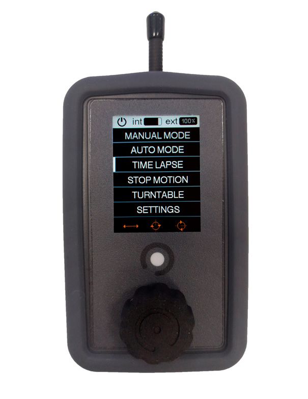
Tabla de contenidos                                                                                       Español

         ¿Qué incluye?              ............................................................................................3
         Puesta en marcha           ............................................................................................4
         Control del Slider         ............................................................................................6
         Uso del mando              ............................................................................................6
         Modo manual                ............................................................................................6
         Modo Auto                  ............................................................................................6
         Modo Timelapse             ............................................................................................7
         Modo Stop Motion           ............................................................................................8
         Modo Multipunto            ............................................................................................10
         Includes                   ............................................................................................11
         Set-up                     ............................................................................................12
         Portable Wirecam control   ............................................................................................14
         Using the remote           ............................................................................................14
         Manual mode                ............................................................................................14
         Auto Mode                  ............................................................................................14
         Timelapse Mode             ............................................................................................15
         Stop motion mode           ............................................................................................16
         Multipoint mode            ............................................................................................18

Pág. 2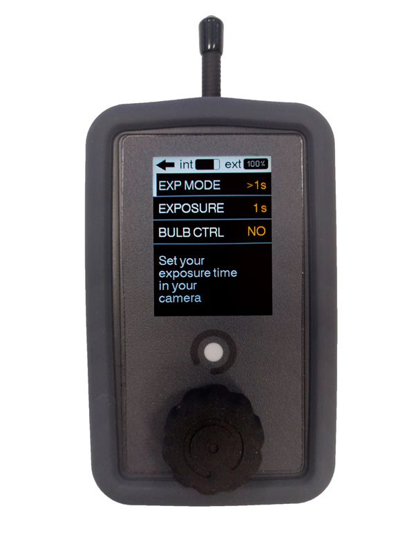
¿Qué incluye?                                                   Español

          1.   Cablecam
          2.   Mando de control inalámbrico
          3.   Carcasa de silicona de protección para el mando
          4.   Batería Li-ion de 12V
          5.   Cable microUSB (para actualizaciones de firmware)
          6.   Cable USB (para el mando)
          7.   Alimentador/cargador 12V
          8.   100 metros de Cable Nylon monofilamento de 2,5 mm de diámetro

Pág. 3
Puesta en marcha                                                                       Español

            Montaje de línea:
            1. Ate la cuerda en un extremo asegurándose de que el punto de anclaje pueda aguantar la tensión
            de la línea.
            2. En el otro extremo utilizar un tensor, teniendo un punto de anclaje fuerte. Hacer una lazada a la
            cuerda y utilice el tensor para unir el punto de anclaje y la lazada hecha.
            3. Montar el VR360 Minicablecam en la línea apoyando en la parte inferior de las 2 poleas de los
            extremos y pasarla por la parte superior de la polea central.

            Montaje en cámara:
            1. Enroscar la cámara en el tornillo de ¼ en la placa de anclaje.
            2. Acoplar la placa en la base de la Portable Wirecam.

            Encendido de la VR360 Minicablecam:
            1. Conectar la batería a la entrada de alimentación de la caja electrónica.
            2. Mantener pulsado el botón de encendido hasta que escuche dos breves pitidos.

            Encendido de mando de control:
            1. Mantener pulsado el botón central hasta que la pantalla se encienda.
            2. Girar el botón central en cualquier dirección hasta completar la línea de la pantalla.

            Sincronización:
            1. La sincronización entre el VR360 Minicablecam y el mando de control es automática.
            2. Una vez encendidos, la aparición de la barra indicadora del nivel de batería EXT significará que ya
            se ha establecido la conexión entre el mando y la wirecam.
            NOTA: Si el indicador de batería EXT (1) vemos un rectángulo con una línea diagonal en su interior,
            significa que no hay conexión. Comprobar que el mando y el dispositivo se encuentren en el mismo
            canal a través de la pantalla de settings en el mando de control.

Pág. 4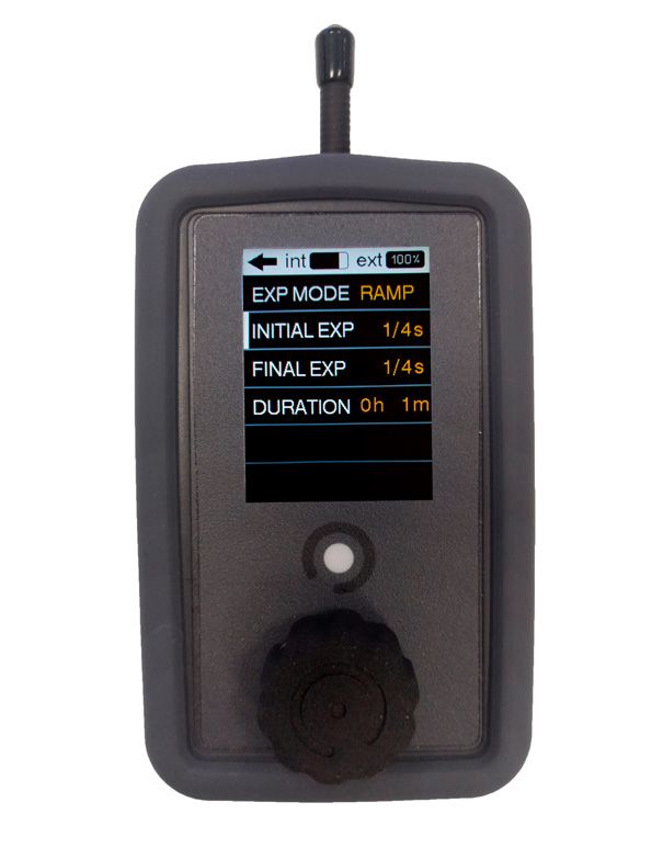
Español

         Carga de baterías:
         1.Conectar el conector macho del cargador al conector hembra de la batería.
                90 mins = 80% de carga (tiempo aproximado)
                150 mins = 100% de carga (tiempo aproximado)
         2.Es posible cargar varias baterías conectándolas en serie y conectando el cargador a una de ellas.
         NOTA: Si la batería está enchufada al Compact Slider y este está encendido, el tiempo de carga au-
         mentará.

         Cargar mando de control:
         1. Conectar cable USB al mando de control y a algún puerto USB de carga.

         Conocer estado de la carga:
         1. Desconectar la batería del cargador.
         2. Conectar la batería al VR360 Minicablecam.
         3. Encender el VR360 Minicablecam y el mando de control.
         4. Comprobar el nivel de batería EXT en la pantalla del mando de control.

         Consejos y advertencias:
         1. Puede dejar el cargador/alimentador conectado a las baterías sin que ello suponga ningún riesgo
         o deterioro de la batería por sobrecarga.
         2. Debido a la dependencia que existe entre los dos parámetros de velocidad, podemos llegar a una
         situación de bloqueo mutuo a la hora de elegir las velocidades, donde el margen en el que podemos
         mover las velocidades es muy pequeño. Esta situación es más probable con recorridos muy cortos y
         porcentajes bajos de rampa, y podemos salir de ella aumentado la rampa.

         Descargo de responsabilidad:
         Noxon no se hace responsable por daños ocasionados por uso impropio o modificaciones realizadas
         al producto.

Pág. 5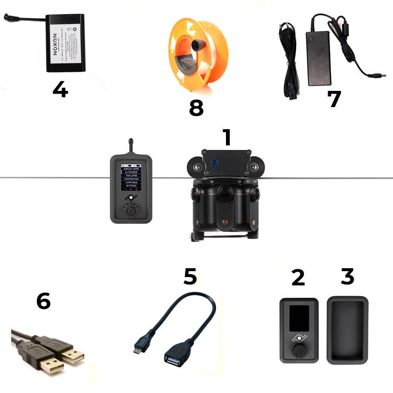
Control de la VR360 Minicablecam                                                              Español

                    Uso del mando:
                    1. Para desplazarse por el menú, gire la perilla de control.
                    2. Pulsación corta de la rueda de control: seleccionar/entrar/activar/ejecutar.
                    3. Pulsación larga de la rueda de control: realiza la acción de salir/volver/terminar/apagar.

                    Manual mode: Permite controlar el movimiento en tiempo real.
                    • El giro de la perilla provocará un aumento o disminución de la velocidad en uno de los dos sentidos
                    de giro.
                    • Una pulsación de la perilla provocará el paso directo a velocidad 0.
                    NOTA: Una pérdida de conexión entre el mando y el aparato provocará también una frenada de se-
                    guridad.

                    Auto mode: Permite programar un recorrido y reproducirlo cuando se quiera con diferentes paráme-
                    tros de aceleración y velocidad.
                    Movimiento automático de un solo tramo
                    • Pulsar la perilla situando el cursor en la línea de desplazamiento.
                    • Moviendo la rueda del mando es posible mover el eje y haciendo click para establecer la posición
                    inicial del movimiento.
                    • Una doble pulsación rápida retrocederá en la secuencia de grabación, permitiendo cambiar puntos
                    previamente establecidos.
                    • Una vez se hayan establecido todos los puntos necesarios, manteniendo pulsada la perilla se termi-
                    nará la programación y el aparato llevará el eje al punto inicial que se haya establecido.
                    • Una vez grabados los puntos, se pueden definir los parámetros de velocidad (SPEED1) y acelera-
                    ción (RAMP).
                             SPEED1: Define la velocidad en una escala del 1 al 40. Es posible que el sistema nos limite
                    la selección de velocidades debido a que la distancia disponible no es suficiente para alcanzar las
                    velocidades más altas.
                             RAMP: Define el porcentaje del recorrido que se usará para acelerar y decelerar. Las acelera-
                    ciones tendrán siempre un perfil simétrico, es decir, se reservará la misma distancia para acelerar que
                    para frenar.
                             REPEAT: Podemos elegir entre un movimiento repetitivo que reproduce el tramo programado
                    sucesivamente hacia adelante y hacia atrás. Una pulsación de la perilla hará que el movimiento se
                    detenga y el aparato vuelva a la posición inicial.
                             GO: Una pulsación con el cursor sobre GO lanza la secuencia de arranque del movimiento.

Pág. 6
Español
Movimiento automático de dos tramos
Cada eje de movimiento tendrá estas opciones a lo largo del movimiento:
• Se mantiene estático durante los dos tramos.
• Se mantiene estático el primer tramo y se mueve el segundo.
• Se mueve el primer tramo y se mantiene estático el segundo.
• Se mueve durante los dos tramos en la misma dirección.
• Se mueve durante los dos tramos, invirtiendo la dirección de un tramo a otro.
NOTAS: Para tener un movimiento de dos tramos, se debe tener al menos algún movimiento en cada
uno de los dos tramos, aunque estos movimientos correspondan a dos ejes distintos.
Los intervalos de aceleración y deceleración dependerán en este caso de cuál de los dos tramos es
el de mayor velocidad. Si el primer tramo se debe realizar a mayor velocidad, la desaceleración se
realizará antes de comenzar el segundo tramo, en caso contrario, la aceleración se producirá al inicio
del segundo tramo.
ATENCIÓN: Debido a la dependencia que existe entre los dos parámetros de velocidad, es posible
llegar a una situación de bloqueo mutuo a la hora de elegir las velocidades, donde el margen en el que
podemos mover las velocidades es muy pequeño. Esta situación es más probable con recorridos muy
cortos y porcentajes bajos de rampa, y se puede solucionar aumentado la rampa.
Modo time lapse: Permite reproducir paso a paso un movimiento previamente grabado, generando
señales de disparo para la cámara entre cada paso.
NOTA: La grabación de movimiento en time lapse no se comparte con el modo automático, y al grabar
un movimiento para el modo time lapse se borra el movimiento grabado para el modo automático.
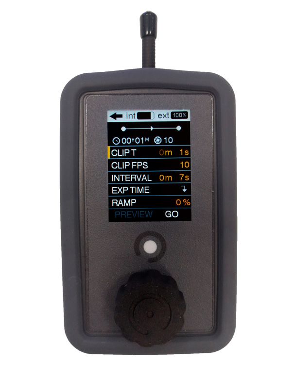
Los parámetros que podemos configurar son los siguientes:
• CLIP T: Es el tiempo que queremos que dure el clip resultante del time lapse.
• CLIP FPS: La velocidad, en fotogramas por segundo, al que compilaremos el clip de video. Se usa
para calcular el número de disparos a realizar.
• INTERVAL: El tiempo entre disparos. Estará limitado por el tiempo mínimo necesario para realizar el
recorrido entre disparos, y el tiempo de exposición.
•EXP TIME: Tiempo de exposición. Seleccionándolo se accede a otro menú donde se define y controla
el tiempo de exposición.
Pág. 7Español
EXP MODE:
1s: Se usa para determinar tiempos de exposición mayores a un segundo. Se pue
de seguir usando exposiciones controladas por la propia cámara o ceder el control
de la exposición a la Portable Wirecam.
Para que el slider pueda controlar la exposición, deberá configurar la cámara en
modo Bulb(B), y seleccionar “YES” en la casilla BULB CTRL del menú del mando.
RAMP: Permite definir una rampa de exposición controlada por el aparato. Los parámetros
que definirán esta rampa de exposición son:
INITIAL EXP: El tiempo de exposición inicial, que se mantendrá constante hasta el
inicio de la rampa
START: Momento de inicio de la rampa, se definirá en términos de tiempo de time
lapse. Es decir, si el resto de parámetros definidos es un time lapse de 2 horas, se
puede variar este parámetro entre el instante 0h 0m y 2h 0m
FINAL EXP: El tiempo de exposición final, que se mantendrá constante desde el
final de la rampa hasta el final del time lapse
FINISH: El momento del final de la rampa, se definirá en términos de tiempo de
tiempo de time lapse. Podrá tomar valores desde el START hasta la duración total
del time lapse.
• RAMP: Permite definir una rampa espacial, haciendo que el desplazamiento entre las fotos iniciales
y las finales sea más corto que el desplazamiento entre las fotos del tramo central. Esta variación del
desplazamiento se ejecuta de forma totalmente controlada y progresiva, y tendrá un efecto de arran-
que y parada suaves en el time lapse una vez se haya compilado.
• PREVIEW/GO: Aparecen una vez se haya grabado un movimiento. Permite hacer una pre visuali-
zación (PREVIEW) donde se ejecuta el movimiento de forma continua, o lanzar la ejecución del time
lapse (GO).
Modo stop motion: Permite reproducir paso a paso un movimiento previamente grabado.
NOTA: La grabación de movimiento en stop motion se comparte con el modo time lapse, pero no con
el modo automático, y al grabar un movimiento para el modo time lapse o stop motion perdemos el
movimiento grabado para el modo automático.
Pág. 8Español
Los parámetros que podemos configurar para definir la ejecución del time lapse son los siguientes:
• CLIP T: Es el tiempo que se quiere que dure el clip resultante del stop motion.
• CLIP FPS: La velocidad, en fotogramas por segundo, al que se compilará el clip de video. Se usa
para calcular el número de disparos a realizar.
• RAMP: Permite definir una rampa espacial, haciendo que el desplazamiento entre las fotos iniciales
y las finales sea más corto que el desplazamiento entre las fotos del tramo central.
• PREVIEW/GO: Aparecen una vez se haya grabado un movimiento. Permite hacer una pre visuali-
zación (PREVIEW) donde se ejecuta el movimiento de forma continua, o lanzar la ejecución del stop
motion (GO).
• GO-TO-0/RESUME: Aparecen una vez se haya lanzado el stop motion y se vuelve al menú del
stop-motion habiendo dejado el slider en un fotograma diferente al inicial. Permite finalizar la ejecución
del stop motion y volver a la posición inicial (GO-TO-0) o volver a la pantalla de ejecución del stop mo-
tion, para continuar con el proceso (RESUME). Cuando estas opciones están visibles, no es posible
cambiar los parámetros (CLIP T, CLIP FPS, RAMP) del stop motion sin haber finalizado su ejecución.
En la pantalla de proceso del stop motion es posible ir fotograma a fotograma, tanto hacia adelante
como hacia atrás, pulsando la perilla de control. Girando la perilla podrá seleccionar esta dirección.
Para saltar a un fotograma cualquiera, seleccionar el indicador numérico de fotograma actual, hacer
click sobre él, y modificarlo. El aparato hará un movimiento continuo hasta el fotograma indicado.
Si mantiene pulsada la perilla de control, volverá a la pantalla anterior de configuración del stop motion
dejando el aparato en ese fotograma, y manteniendo el control sobre la posición, pudiendo volver a
través de la opción RESUME.
ATENCIÓN: Si accede a un modo de funcionamiento distinto al STOP MOTION, arranca la secuen-
cia de grabación de un nuevo movimiento, o apaga el slider, perderá la traza de la posición y deberá
arrancar un nuevo STOP MOTION. El apagado o la desconexión del mando, sin embargo, no tendrá
estas consecuencias.
Pág. 9Español
Modo multipunto: Permite crear secuencia de movimiento con control temporal. El movimiento será
de un solo eje.
1. Introducir los puntos del recorrido moviendo el aparato y marcando las posiciones con la perilla de
control, o introduciéndolos numéricamente en una tabla.
2. Los puntos grabados moviendo y marcando las posiciones con la perilla de control se reflejarán en
esa misma tabla editable, por lo que también es posible corregir o modificar a mano
3. Configurar los tiempos editando los valores en la tabla. Los valores serán el momento en el que se
desea que el aparato alcance la posición indicada y el tiempo que se desea que permanezca inmóvil.
Ajustes/Settings
• Brightness (Brillo): Permite ajustar el brillo de la pantalla en una escala del 1 al 10.
• Delay Start (Retardo inicial): Es el lapso del tiempo que transcurre entre la pulsación para iniciar el
movimiento programado y el comienzo real del movimiento. Es configurable en pasos de 5 segundos
con un rango entre 0 (anulando el retardo) y 60 segundos.
• Remote Auto-Off (Auto apagado del mando): Activa el auto apagado del mando tras 10 minutos de
inactividad.
• Controller Auto-Off (Auto apagado del sistema de movimiento): Activa el auto apagado del sistema
de movimiento del Compact Slider tras 10 minutos de inactividad).
• LCD Auto-Off (Auto apagado LCD): Auto apagado de la pantalla tras 60 segundos de inactividad.
• Beep: Activa la reproducción de un pitido justo antes del comienzo de un movimiento automático.
• RF Channel (Selección de canal de radiofrecuencia): seleccionando diferente canal, permite la posi-
bilidad de trabajar con dos aparatos diferentes en un mismo lugar.
• Info: Permite el acceso a la pantalla donde se muestra la información acerca de la versión de firmwa-
re del mando, del sistema de movimiento y el número de serie. También posibilita la activación del
modo de actualización de firmware.
Pág. 10Includes English
1. Cablecam
2. Wireless remote controller
3. Protective silicone case for the remote controller
4. 12V Li-ion battery
5. MicroUSB wire (for firmware updates)
6. USB wire (for remote controller)
7. 12V power supply/charger
8. 100 meters of nylon monofilament cable of 2.5 mm/diameter
Pág. 11Set up English
Setting the line:
1. Tie the rope at one end making sure the anchor point can withstand the tension of the line.
2. At the other end use a turnbuckle, having a strong anchor point. Make a loop to the rope and use
the tensioner to join the anchor point and the loop made.
3. Mount the VR360 Minicablecam on the line resting on the lower part of the 2 end pulleys and pass
it through the upper part of the central pulley.
Camera mounting:
1. Screw the camera into the ¼ screw in the anchor plate.
2. Attach the plate to the base of the Portable Wirecam.
Turning on the VR360 Minicablecam:
1. Connect the battery to the power input of the electronic box.
2. Press and hold the power button until you hear two short beeps.
Turning on the wireless controller:
1. Press and hold the center button until the screen turns on.
2. Rotate the center knob in any direction to complete the line on the screen.
Synchronization:
1. The synchronization between the VR360 Minicablecam and the wireless controller is automatic.
2. Once turned on, the appearance of the EXT battery level indicator bar will mean that the connec-
tion between the controller and the wirecam has already been established.
NOTE: If the EXT battery indicator (1) we see a rectangle with a diagonal line inside it, it means that
there is no connection. Check that the remote control and the device are on the same channel throu-
gh the settings screen on the remote control.
Pág. 12English
Battery charging:
1. Connect the male connector of the charger to the female connector of the battery.
90 mins = 80% charge (approximate time)
150 mins = 100% charge (approximate time)
2. Multiple batteries can be charged by connecting them in series and connecting the charger to one
of them.
Charging the wireless controller:
1. Connect the USB cable to the controller and to a USB charging port.
Check charge level:
1. Disconnect the battery from the charger.
2. Connect the battery to the VR360 Minicablecam.
3. Turn on the VR 360 Minicablecam and the hand control.
4. Check the EXT battery level on the hand control display.
Tips and Warnings:
1. You can leave the charger / power supply connected to the batteries without posing any risk or
deterioration of the battery due to overcharging.
2. Due to the dependence that exists between the two speed parameters, we can reach a situation of
mutual blocking when choosing the speeds, where the margin in which we can move the speeds is
very small. This situation is more likely with very short routes and low ramp percentages, and we can
get out of it by increasing the ramp.
Disclaimer:
Noxon is not responsible for damage caused by improper use or modifications made to the product.
Pág. 13VR360 Minicablecam Control English
Using the remote:
1. To scroll through the menu, turn the control knob.
2. Short press on the control wheel: select / enter / activate / execute.
3. Long press on the control wheel: perform the exit / return / end / power off action.
Manual mode: Allows you to control the movement in real time.
• Turning the knob will cause the speed to increase or decrease in one of the two directions of rota-
tion.
• One press of the knob will cause direct passage to speed 0.
NOTE: A loss of connection between the control and the device will also cause a safety braking.
Auto mode: Allows you to program a movement and play it whenever you want with different accele-
ration and speed parameters.
Single-section automatic movement
• Press the knob by positioning the cursor on the scroll line.
• By moving the control knob it is possible to move the axis and by clicking to establish the initial
position of the movement.
• A quick double press will go back in the recording sequence, allowing you to change previously set
points.
• Once all the necessary points have been established, keeping the knob pressed will finish the pro-
gramming and the device will take the axis to the initial point that has been established.
• After the points have been recorded, the speed (SPEED1) and acceleration (RAMP) parameters
can be set.
SPEED1: Defines the speed on a scale from 1 to 40. It is possible that the system limits the
selection of speeds due to the fact that the available distance is not enough to reach the highest
speeds.
RAMP: Defines the percentage of travel that will be used to accelerate and decelerate.
Accelerations will always have a symmetrical profile, that is, the same distance will be reserved for
accelerating as for braking.
REPEAT: We can choose between a repetitive movement that reproduces the programmed
section successively forward and backward. One press of the knob will stop the movement and re-
turn the appliance to the initial position.
GO: A press with the cursor on GO launches the movement start sequence.
Pág. 14English
Two-section automatic movement
Each axis of movement will have these options throughout the movement:
• Remains static during the two sections.
• The first section remains static and the second one moves.
• The first section is moved and the second remains static.
• It moves during the two stages in the same direction.
• It moves during the two sections, reversing the direction from one section to another.
NOTES: To have a movement of two sections, you must have at least some movement in each of the
two sections, although these movements correspond to two different axes.
The acceleration and deceleration intervals will depend in this case on which of the two sections is
the faster one. If the first section must be carried out at a higher speed, the deceleration will take
place before starting the second section, otherwise, the acceleration will occur at the beginning of the
second section.
WARNING: Due to the dependence that exists between the two speed parameters, it is possible to
reach a situation of mutual blocking when choosing the speeds, where the margin in which we can
move the speeds is very small. This situation is more likely with very short runs and low ramp percen-
tages, and can be addressed by increasing the ramp.
Time lapse mode: It allows you to play back a previously recorded movement step by step, genera-
ting trigger signals for the camera between each step.
NOTE: Time lapse motion recording is not shared with automatic mode, and recording a movement
for time lapse mode erases the recorded motion for automatic mode.
The parameters that we can configure are the following:
• CLIP T: It is the time we want the clip resulting from the time lapse to last.
• CLIP FPS: The speed, in frames per second, at which we will compile the video clip. It is used to
calculate the number of shots to take.
• INTERVAL: The time between shots. You will be limited by the minimum time necessary to make
the trip between shots, and the exposure time.
• EXP TIME: Exposure time. Selecting it leads to another menu where the exposure time is defined
and controlled.
Pág. 15English
EXP MODE:
1s: Used to determine exposure times greater than one second. You can still use
exposures controlled by the camera itself or give control of the exposure to the
VR360 Minicablecam.
In order for the slider to control the exposure, you must set the camera to Bulb (B)
mode, and select “YES” in the BULB CTRL box on the remote’s menu.
RAMP: It allows defining an exposure ramp controlled by the device. The parameters that will
define this exposure ramp are:
INITIAL EXP: The initial exposure time, which will remain constant until the start of
the ramp
START: Starting moment of the ramp, it will be defined in terms of time lapse time.
That is, if the rest of the parameters defined is a time lapse of 2 hours, this parame
ter can be varied between the instant 0h 0m and 2h 0m
FINAL EXP: The final exposure time, which will remain constant from the end of the
ramp to the end of the time lapse
FINISH: The moment of the end of the ramp, it will be defined in terms of time of time
of time. It can take values from START to the total duration of the time lapse.
• RAMP: Allows you to define a spatial ramp, making the displacement between the initial and final
photos shorter than the displacement between the photos in the central section. This variation of
scrolling runs in a fully controlled and progressive manner, and will have a smooth start and stop
effect on time lapse once compiled.
• PREVIEW / GO: Appear once a movement has been recorded. It allows to make a preview (PRE-
VIEW) where the movement is executed continuously, or to launch the execution of the time lapse
(GO).
Stop motion mode: Allows you to play a previously recorded movement step by step.
NOTE: The stop motion motion recording is shared with the time lapse mode, but not with the au-
tomatic mode, and when recording a movement for the time lapse or stop motion mode we lose the
motion recorded for the automatic mode.
Pág. 16English
The parameters that we can configure to define the execution of the time lapse are the following:
• CLIP T: It is the time that you want the clip resulting from the stop motion to last.
• CLIP FPS: The rate, in frames per second, at which the video clip will be compiled. It is used to
calculate the number of shots to take.
• RAMP: Allows you to define a spatial ramp, making the displacement between the initial and final
photos shorter than the displacement between the photos in the central section.
• PREVIEW / GO: Appear once a movement has been recorded. It allows making a preview (PRE-
VIEW) where the movement is executed continuously, or launching the execution of stop motion
(GO).
• GO-TO-0 / RESUME: They appear once the stop motion has been launched and it returns to the
stop-motion menu having left the slider in a different frame than the initial one. It allows ending the
stop motion execution and returning to the initial position (GO-TO-0) or returning to the stop motion
execution screen, to continue with the process (RESUME). When these options are visible, it is not
possible to change the parameters (CLIP T, CLIP FPS, RAMP) of the stop motion without having
finished its execution.
On the stop motion process screen, it is possible to go frame by frame, both forward and backward,
by pressing the control knob. By turning the knob, you can select this direction.
To jump to any frame, select the current frame numerical indicator, click on it, and modify it. The unit
will make a continuous movement until the indicated frame.
If you keep the control knob pressed, you will return to the previous stop motion configuration screen,
leaving the device in that frame, and maintaining control over the position, being able to return throu-
gh the RESUME option.
WARNING: If you access an operating mode other than STOP MOTION, start the recording sequen-
ce of a new movement, or turn off the slider, you will lose track of the position and have to start a new
STOP MOTION. Switching off or disconnecting the controller, however, will not have these conse-
quences.
Pág. 17English
Multipoint mode: It allows creating movement sequence with time control. The movement will be
single axis.
1. Enter the travel points by moving the apparatus and marking the positions with the control knob, or
entering them numerically in a table.
2. The points recorded by moving and marking the positions with the control knob will be reflected in
that same editable table, so it is also possible to correct or modify by hand
3. Set the times by editing the values in the table. The values will be the moment in which you want
the device to reach the indicated position and the time you want it to remain immobile.
Settings / Settings
• Brightness: Adjusts the screen brightness on a scale of 1 to 10.
• Delay Start: This is the amount of time that elapses between the press to start the programmed
movement and the actual start of the movement. It is configurable in steps of 5 seconds with a range
between 0 (canceling the delay) and 60 seconds.
• Remote Auto-Off: Activates the remote’s auto-off after 10 minutes of inactivity.
• Controller Auto-Off: Activates the Compact Slider motion system auto-off after 10 minutes of inacti-
vity.
• LCD Auto-Off: Auto turn off the screen after 60 seconds of inactivity.
• Beep: Activates the playback of a beep just before the start of an automatic movement.
• RF Channel (Radio frequency channel selection): selecting a different channel allows the possibility
of working with two different devices in the same place.
• Info: Allows access to the screen where information about the firmware version of the remote con-
trol, the motion system and the serial number is displayed. It also enables activation of the firmware
update mode.
Pág. 18También puede leer