Prototype of lineal solar collector Fresnel: revista UD
←
→
Transcripción del contenido de la página
Si su navegador no muestra la página correctamente, lea el contenido de la página a continuación
Preparación de Artículos revista VISIÓN ELECTRÓNICA: algo más que un estado sólido
 Fecha de envío: 17 de noviembre de 2019
 Fecha de recepción: 14 de enero de 2020
 Fecha de aceptación: 28 de enero de 2020
A research vision

 Prototype of lineal solar collector Fresnel:
 Artesanal system for the production of hot water and/or water vapor

 Prototipo de colector solar lineal Fresnel:
 Sistema artesanal para la producción de agua caliente y/o vapor de agua
 Brayan Eduardo Tarazona-Romero 1, Álvaro Campos-Celador 2,
 Yecid Alfonso Muñoz-Maldonado 3, Camilo Leonardo Sandoval-Rodríguez 4,
 Javier Gonzalo Ascanio-Villabona 5

Cite this article as: B. E. Tarazona-Romero, Á. Campos-Celador, Y. A. Muñoz-Maldonado, C.
L. Sandoval-Rodríguez and J. G. Ascanio-Villabona, “Prototype of lineal solar collector Fresnel:
artesanal system for the production of hot water and/or water vapor”, Visión electrónica, algo
más que un estado sólido, vol. 14, no. 1, pp. xx, january - june 2020. doi: xx

Abstract: The development of a prototype linear solar collector Type Fresnel, has a purpose

the use of direct solar heat radiation for water heating and/or steam production, as an alternative

to supply conventional water heating systems or steam generators, which consume energy

from fossil fuels.

1BSc. in Electromechanical Engineering, Unidades Tecnológicas de Santander, Colombia. MSc. in Renewable
energy and energetic efficiency, Universidad a Distancia de Madrid, España. Current position: Unidades
Tecnológicas de Santander, Colombia. E-mail: btarazona@correo.uts.edu.co ORCID: https://orcid.org/0000-
0001-6099-0921
2BSc. in Industrial Engineering, PhD in Thermal Engineering, Escuela Técnica Superior de Ingeniería de Bilbao,
España. Current position: Universidad del País Vasco UPV/EHU, España. E-mail: alvaro.campos@ehu.eus
ORCID: https://orcid.org/0000-0002-5628-8192
3BSc. in Electronic Engineering, Universidad Antonio Nariño, Colombia. PhD. In Energy technology, Universidad
Politécnica de Valencia-Internacional, España. Current position: Universidad Autónoma de Bucaramanga,
Colombia. E-mail: ymunoz294@unab.edu.co ORCID: https://orcid.org/0000-0002-5213-1884
4 BSc. in Electronic Engineering, MSc. in Electronic, Universidad Industrial de Santander, Colombia. Current
position: Unidades Tecnológicas de Santander, Colombia. E-mail: csandoval@correo.uts.edu.co ORCID:
https://orcid.org/0000-0001-8584-0137
5BSc. in Electromechanical Engineering, Unidades Tecnológicas de Santander, Colombia. MSc. in Renewable
energy and energetic efficiency, Universidad a Distancia de Madrid, España. Current position: Unidades
Tecnológicas de Santander, Colombia. E-mail: jascanio@correo.uts.edu.co ORCID: https://orcid.org/0000-0003-
1749-5399
Preparación de Artículos revista VISIÓN ELECTRÓNICA: algo más que un estado sólido
 Fecha de envío: 17 de noviembre de 2019
 Fecha de recepción: 14 de enero de 2020
 Fecha de aceptación: 28 de enero de 2020
For the development of the system, used the solar radiation of the UTS, located in

Bucaramanga, Colombia, is identify the mathematical models to perform the sizing, then

materials based on technical specifications and availability in Colombia, in order to perform the

assembly and field tests, measuring the ambient and in the collector temperature to determine

the efficiency of the model.

It should be noted that, the model presented does not have a control system for flow,

temperature, pressure and level, it has no solar tracking of any kind; Its movement was done

manually with each reflex. Finally, the model does not have a hydraulic system forced, and has

a preheater at the entry of the concentration point.

Keywords: Optical efficiency, reflection system, solar collector, solar radiation, steam

production.

Resumen: El desarrollo de un prototipo de colector solar lineal Tipo Fresnel tiene como

finalidad el aprovechamiento de la radiación solar directa en calor para el calentamiento de

agua y/o la producción de vapor, como alternativa para suplir los sistemas de calentamiento

de agua o generadores de vapor convencionales, que consumen energía proveniente de

combustibles fósiles.

Para el desarrollo del sistema, se utiliza la radiación solar de las UTS, ubicada en

Bucaramanga, Colombia, se identifican los modelos matemáticos para realizar el

dimensionamiento, posteriormente se seleccionan materiales basados en especificaciones

técnicas y disponibilidad en Colombia, con el fin de realizar el montaje y realizar pruebas en

campo, midiendo la temperatura ambiente y en el colector para determinar la eficiencia del

modelo.
Preparación de Artículos revista VISIÓN ELECTRÓNICA: algo más que un estado sólido
 Fecha de envío: 17 de noviembre de 2019
 Fecha de recepción: 14 de enero de 2020
 Fecha de aceptación: 28 de enero de 2020
Cabe resaltar, que el modelo presentado no cuenta con sistema de control de flujo,

temperatura, presión y nivel, no tiene seguimiento solar de ningún tipo; el movimiento del

mismo se realizó manualmente con cada reflecto. Por último, el modelo no cuenta con sistema

hidráulico de tiro forzado, y tiene un precalentador a la entrada del punto de concentración.

Palabras clave: Eficiencia óptica, sistema de reflexión, colector solar, radiación solar,

producción de vapor.

 1. Introduction

Accelerated population growth, technological development, industrialization and urbanization

increase the energy demands of developing countries around the world [1]. Solar energy is the

source of clean energy that is available in most regions of the world, it is economical and infinite

[2]. In addition to this, there are several technologies for harnessing solar radiation, solar

concentration energy is one of the most promising forms [3], in which the linear Fresnel [4] [5]

reflector [6] [7] is highlighted [8] [9], is one of the main Concentration solar systems [10] [11] to

produce useful heat at medium and high temperature levels [12], additionally it is a low-cost

technology that has sufficient thermal efficiency and, therefore, is characterized as an

interesting and valuable option to use solar irradiation [2]. In turn, the development of clean

energy is essential to combat climate change and reduce the damage associated with the

production of fossil fuels, we have seen in recent years an increase in the temperature of the

planet to the point of having record levels of high temperatures in different parts of the world

[13].

Nationally, the energy production during May 2018 in Colombia was 186.5 GWh / day, of which

85.68% originated from renewable fuels (84.97% hydraulic, 0.64% biomass, 0.05% wind and
Preparación de Artículos revista VISIÓN ELECTRÓNICA: algo más que un estado sólido
 Fecha de envío: 17 de noviembre de 2019
 Fecha de recepción: 14 de enero de 2020
 Fecha de aceptación: 28 de enero de 2020
0.02% solar), while the remaining 14.32% corresponded to non-renewable fossil fuels such as

coal, oil or natural gas. Although Colombia produces largely through clean energy, these are at

risk, since the greatest production comes from reservoirs and they are put at risk when their

levels drop, increasing the use of fossil fuels [14].

It is important to potentiate the generation of energy with the implementation of new

technologies, taking into account that Colombia is a country with a geographical diversity, with

different climatic conditions evaluated in different weather stations [15], in which we can easily

implement any type of system renewable energy, either by solar panels, wind turbines, tidal

among others.

In order to take advantage of this energy resource effectively, the design and construction of a

prototype of a linear solar collector type Fresnel is exposed, which is a relatively new technology

which presents a mirror arrangement called primary reflector system, its function is to direct the

direct solar radiation to a heat receiving tube located at a certain height, when the radiation

comes into contact with the surface of the tube it is transformed into thermal energy by

transferring it to a liquid carrier liquid, in order to store thermal energy or to generate electricity.

 2. Methodology

The research methodology is descriptive type [16] ,with a quantitative approach [17] [18] and

its methodological development is proposed starting with obtaining information from scientific

sources such as top articles and books, in order to identify mathematical models that determine

the sizing parameters, to subsequently perform the modeling of the system in a CAD software,

obtaining real plans for the subsequent construction of the model at low manufacturing cost so

that it is viable and feasible as a source of water heating and / or steam generation. Finally,
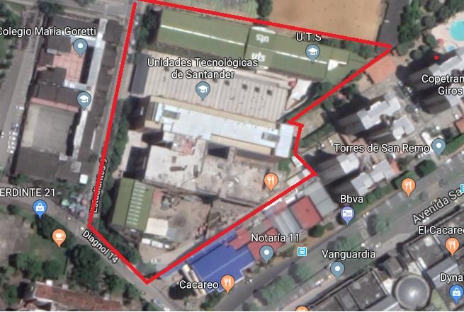
Preparación de Artículos revista VISIÓN ELECTRÓNICA: algo más que un estado sólido
 Fecha de envío: 17 de noviembre de 2019
 Fecha de recepción: 14 de enero de 2020
 Fecha de aceptación: 28 de enero de 2020
field tests will be carried out to see the real functioning of the prototype and analyze them in

order to determine their optical efficiency.

 3. Sizing of Fresnel Linear Collector

For the development of the mathematical models that will allow the dimensioning of the Fresnel

type linear collector, the geographical identification of the area in which the field tests will be

carried out with the prototype to be developed is initially carried out. The site has the following

geographical coordinates: Latitude 7.1 and longitude -73.12, with an elevation of 930 m above

sea level, additionally listed in Table 1.

 Table 1. Geographic coordinates of the site.

 Geographical Coordinates
 Place Elevation
 Latitude Longitude
 UTS 7,1 - 73,12 930 m
 Source: own.

 Figure 1. Site, [19].
Preparación de Artículos revista VISIÓN ELECTRÓNICA: algo más que un estado sólido Fecha de envío: 17 de noviembre de 2019 Fecha de recepción: 14 de enero de 2020 Fecha de aceptación: 28 de enero de 2020 A search of the geographical area for the implementation is carried out, supported by the Google Maps tool of free access, in which it is searched and selected with the data or geographical coordinates of Table 1, the place selected was, the Technological Units of Santander - UTS, Bucaramanga, Colombia. Figure 1 shows the infrastructure of the UTS, marked in red. For the development of the dimensioning calculations of the Fresnel linear collector, some considerations were taken, taking into account that it was the development of a prototype, some parameters were defined to start the execution of the mathematical models and have an idea of their operation, keeping a relationship with existing projects at industrial level in plants and laboratory scale models. These parameters are: Focal length of the system: 75 cm. Mirror area (Unit): 10 cm * 100 cm. The reflector system is made up of 10 mirrors. The working time interval of the system is from 9 am to 15 pm. The secondary concentration system consists of a U-shaped collector tube or coil that has a total length of 2 m and a diameter of 3/8’. Initially, the parameters that define the position of the reflectors in terms of distance and angle of inclination were calculated, this calculation was made taking into account the considerations or parameters defined above and the date on which the system was evaluated. The date on which it was evaluated was February 26, 2019, so it has a Nd = 57. With that data, the solar inclination was calculated taking into account equation (1). 284+57 = 23,45 (360 ( )) = −9,41° (1) 365
Preparación de Artículos revista VISIÓN ELECTRÓNICA: algo más que un estado sólido
 Fecha de envío: 17 de noviembre de 2019
 Fecha de recepción: 14 de enero de 2020
 Fecha de aceptación: 28 de enero de 2020

Subsequently, the hour angle was calculated with the initial working time of the system, that is,

Nh = 9 hours evidenced in equation (2).

 = 15(9 − 12) = −45° (2)

At the same time, it is reflected in equation (3), the approach of calculating the angle of solar

incidence, taking into account the latitude cited in Table 1 of the place or location of

implementation of the system to be developed and the calculation of the solar inclination

calculated in equation (1).

 cos(θ) = [sin(7,1) ∗ sin(−9,41)] + [cos(7,1) ∗ cos(−45) cos(−9,41)] (3)

As a result of equation (3), it is obtained that the solar incidence angle equal to 47.77 °. In turn,

the angle of solar height raised below in equation (4) is calculated.

 = 90 − 47,77° (4)

As a result of equation (4), the angle of solar height equal to 42.33 ° is obtained. Once the initial

parameters were obtained from the geographic data, the variables that define the position and

separation of the reflectors are determined, thus: in the first instance, to perform the geometric

design of the primary reflectors, the first reflector was located just below the test. receiver, and

then the next reflector was located on the right side.

There are 7 parameters or variables immersed in the location of the first reflex, of which 6 have

been defined and / or calculated 6 expressed below: L1 = 0, = 0, ϴ = 47.77°, ϒ = 42.23°, W

= 10 cm, h = 75 cm.

Subsequently, the angle of inclination of the first reflector raised in equation (5) is calculated to

complete the 7 parameters mentioned above.
Preparación de Artículos revista VISIÓN ELECTRÓNICA: algo más que un estado sólido
 Fecha de envío: 17 de noviembre de 2019
 Fecha de recepción: 14 de enero de 2020
 Fecha de aceptación: 28 de enero de 2020
 47,77°+0
 = (5)
 2

As a result of equation (5), the angle of inclination of the first reflector is obtained which is:

23.88 °. Then, the separation distance of the second reflector is calculated.

Equation (6), allows to calculate the separation distance of the second reflector from the first.

As a result of equation (6) a separation of 13.6 cm was obtained.

 sin(23,88)
 2 = 10 (tan(42,23) + cos(23,88)) (6)

Subsequently, the Angle formed between the vertical axis of the receiver and the reflected solar

radiation with a value of 10.3 and the angle of inclination of the second reflector is determined

by a value of 29 °.

Likewise, the same procedure will be developed to determine the values of the following three

reflectors corresponding to the right side of the receiver, in which the inclination, angle , and

the separation distance between reflectors are calculated, these results are recorded in the

Table 2.

 Table 2. Data corresponding to the location of the reflectors on the right side of the receiver.

 Ei Li-1 ---- Li(cm) Li(cm) Φi° βi°
 E1 0 0 0° 23,88°
 E2 13,6 13,6 10,3° 34°
 E2 14,1 27,7 20,3° 38,55°
 E4 14,45 42,15 29,33° 38,55°
 E5 14,7 56,85 37,16° 42,46°
 Source: own.

Where, Li-1 ---- Li(cm) is the distance between a reflector and the previous one and, Li (cm) is

the distance between the vertical axis of the receiver and the corresponding reflector.
Preparación de Artículos revista VISIÓN ELECTRÓNICA: algo más que un estado sólido
 Fecha de envío: 17 de noviembre de 2019
 Fecha de recepción: 14 de enero de 2020
 Fecha de aceptación: 28 de enero de 2020
Taking into account the data shown in Table 2, it was identified that the separation with greater

extension between a mirror or reflector and the other was given in element E5 with a value of

14.7 cm, therefore, it is determined to take this distance as a reference of separation for the

other reflectors. For reasons of mounting the reflectors, the value of 14.7 cm is close to 15 cm

and the mathematical models that were obtained to feed Table 2 are raised again.

Taking into account that the number of reflectors is even (10 reflectors), an adjustment was

made in their location, respecting the symmetry of the geometric plane of the system, for this

reason, the first initial reflector was located at an equal distance 7.5 cm from the vertical axis

of the receiver, from this the other reflectors were located as evidenced in Figure 2.

 Figure 2. Distances between primary reflectors.

 Source: own.

The values previously calculated in Table 2 are adjusted according to the approximation that

was made to facilitate the assembly of the reflector mirrors, obtaining new values of the

mathematical models tabulated in Table 3.
Preparación de Artículos revista VISIÓN ELECTRÓNICA: algo más que un estado sólido
 Fecha de envío: 17 de noviembre de 2019
 Fecha de recepción: 14 de enero de 2020
 Fecha de aceptación: 28 de enero de 2020
 Table 3. Final parameters of the right area mirrors of the prototype.

 Ei Li(cm) Φi° βi°
 E1 7,5 5,71° 26,74°
 E2 22,5 126,7° 32,23°
 E2 37,5 26,56° 37,16°
 E4 52,5 35° 41,38°
 E5 67,5 42° 44,88°

 Source: own.

As for the parameters of the reflectors on the left side by system symmetry, it is kept at an angle

 and the distances of each reflector, as for the angle of inclination changes by the position of

each element with respect to the receiver, the same models, were applied mathematicians used

to obtain Tables 2 and 3, obtaining the values reflected in Table 4.

 Table 4. Final parameters of the mirrors on the left side of the prototype.

 Ei Li(cm) Φi° βi°
 E1 7,5 5,71° 23,8°
 E2 22,5 126,7° 18,31°
 E2 37,5 26,56° 13,37°
 E4 52,5 35° 9,17°
 E5 67,5 42° 5,66°

 Source: own.

Finally, Figure 3 shows the position of each reflector in initial working conditions according to

the information established in Tables 3 and 4, shows the description of the incident solar

radiation when it reaches the reflector and then reflects it in the direction of the tube receiver.
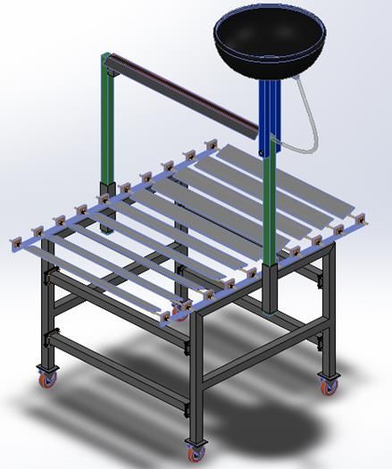
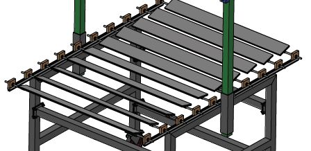
Preparación de Artículos revista VISIÓN ELECTRÓNICA: algo más que un estado sólido
 Fecha de envío: 17 de noviembre de 2019
 Fecha de recepción: 14 de enero de 2020
 Fecha de aceptación: 28 de enero de 2020
 Figure 3. Diagram of the prototype collector geometry.

 Source: own.

 4. CAD Modeling

Figure 4 shows the CAD modeling of the Fresnel mirror linear collector prototype, in which the

trapezoidal cover in which the concentration system goes, the geometrical of the secondary

receiver with a trapezoidal shape without having a secondary reflection system is seen, Without

insulating coating and glass to avoid losses by radiation, convection and conduction, the width

of the mirror is calculated, it was constructed in galvanized sheet 20 gauge, with length of 1.2

m, 3.5 cm high and 12 cm wide.

On the other hand, the receiving tube as mentioned in a previous section has a U-curvature,

with a diameter of 3/8 inch, a length of 2 meters to which a matt black color was applied to

increase its thermal properties, obtaining a theoretical absorptivity coefficient of 0.98 and a

theoretical emissivity coefficient of 0.98.
Preparación de Artículos revista VISIÓN ELECTRÓNICA: algo más que un estado sólido
 Fecha de envío: 17 de noviembre de 2019
 Fecha de recepción: 14 de enero de 2020
 Fecha de aceptación: 28 de enero de 2020

 Figure 4. CAD modeling.

 Source: own.

Additionally, the reflector base was used 1/8 by 1¼ inch hot rolled steel plate, in order to give

consistency to the reflection system, at each end a section of endless screw was welded so

that can serve as a pivot evidenced in Figure 5.
Preparación de Artículos revista VISIÓN ELECTRÓNICA: algo más que un estado sólido
 Fecha de envío: 17 de noviembre de 2019
 Fecha de recepción: 14 de enero de 2020
 Fecha de aceptación: 28 de enero de 2020
 Figure 5. Primary reflection system modeling.

 Source: own.

Also, quadrant brackets with a hole in the center were manufactured in order to be able to

mount on the base of the prototype which was built in a simple way, easy to assemble, with the

purpose of generating ease when performing maintenance or modification of the system in the

future. For the construction of the frame, a 2 inch x 1.5 mm thick square structural tube was

used, 10 cm x 8 cm x 3 mm plates were used for fastening. In turn, to keep the primary reflector

elements fixed, it was determined to use aluminum rails used in the window industry, which

provides ease of sliding of the reflector brackets when locating them.

Finally, after the sizing and CAD modeling of the components of the module, the selection of

the primary reflection system was carried out, which have the following characteristics: flat

mirrors of 3 mm thick glass and a tiny layer of silver (Ag) and on it a layer of protective paint

thus having a reflection coefficient of 95%.
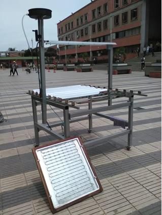
Preparación de Artículos revista VISIÓN ELECTRÓNICA: algo más que un estado sólido
 Fecha de envío: 17 de noviembre de 2019
 Fecha de recepción: 14 de enero de 2020
 Fecha de aceptación: 28 de enero de 2020
 5. Results

The real system is reflected in Figure 6, in which an additional system not mentioned above is

seen that allows preheating the heat transfer fluid entering the zone or concentration point of

the solar radiation directed by the reflector mirrors, this system allows to maintain the system

with a minimum temperature of 45 °C at the entrance of the solar concentration point, this

temperature gradient increases considerably with respect to the type of solar radiation present

at the time of testing, the higher the concentration of direct solar radiation the system efficiency

increases.

 Figure 6. Actual collector prototype.

 Source: own.
Preparación de Artículos revista VISIÓN ELECTRÓNICA: algo más que un estado sólido
 Fecha de envío: 17 de noviembre de 2019
 Fecha de recepción: 14 de enero de 2020
 Fecha de aceptación: 28 de enero de 2020
A series of field tests were carried out, in which it was directly dependent on the solar radiation

present in the area of the collector, in 2019 the climate in Bucaramanga and its metropolitan

area has been affected by rainfall and high cloudiness, directly affecting this type of systems,

for this reason the study was centered in a time slot from 9 am to 12 noon. As a sample, the

results obtained on March 17, 2019 are grouped in Table 5, where the system behaves in terms

of high temperature with better results compared to the other days. At the beginning of the test

an ambient temperature of 28 °C is recorded, reaching a surface temperature in the receiving

tube of 110 °C and an inlet temperature in the heat transfer fluid of 63 °C, the inlet valve is

opened, and As soon as the fluid is supplied to the system, the temperature of the receiving

tube drops to 78 °C, after 7 minutes its temperature rises to 122 °C, two minutes later the

temperature rises to 128 °C, the valve opens outlet and steam is observed with a small amount

of water. As you can see the experiment showed positive results until 11:54 in the morning, on

several occasions the test was affected in most cases by cloudiness.

When taking the records of the flow generated by the CSLF it was detected that the pressure

at the exit of the system is greater than the pressure of the flow meter, it could be observed that

the float indicating the flow reached the limit, leaving in doubt the real measure that the system

flow would have. These types of flowmeters are of millimeter scale, that is, they do not throw

the value of the flow directly, they bring with them correlated tables that deduce the

measurement of the flow depending on the level that the float has reached and the type of the

fluid being treated, therefore The reference device 063-64TA must be used, and according to

its correlation table, it shows a flow of 2000 ml / min at its highest measurement point, which

for the corresponding calculations will be taken as the minimum volumetric flow of the system.
Preparación de Artículos revista VISIÓN ELECTRÓNICA: algo más que un estado sólido
 Fecha de envío: 17 de noviembre de 2019
 Fecha de recepción: 14 de enero de 2020
 Fecha de aceptación: 28 de enero de 2020
 Table 5. One day Data.

 Receiver tube
 Time Process Observation
 temperature
 09:10 a. m. 110°C Water supply Temperature decrease to 78°C
 Steam mixture, minimum quantity of
 09:32 a. m. 121°C Outlet valve
 water
 Steam mixture, minimum quantity of
 09:44 a. m. 128°C Outlet valve
 water
 09:57 a. m. 142°C Outlet valve Steam increase, no water present

 09:58 a. m. 110°C Inlet valve Temperature decrease to 110°C

 10:02 a. m. 100°C Mirror Adjustment Cloudiness
 Steam mixture, minimum quantity of
 10:05 a. m. 132°C Outlet valve
 water
 10:27 a. m. 160°C Outlet valve Steam increase, no water present
 Temperature decrease to 115°,
 10:29 a. m. 115°C Outlet valve
 Cloudiness
 Steam mixture, minimum quantity of
 10:44 a. m. 136°C Outlet valve
 water
 Steam mixture, minimum quantity of
 11:00 a. m. 123°C Outlet valve
 water
 Steam mixture, minimum quantity of
 11:54 a. m. 124°C Outlet valve
 water
 Source: own.

Additionally, the optical efficiency of the system is determined for the field tests performed, for

which the coefficients of the materials involved are estimated, as are the primary reflectors that

contain a thin layer of silver that give a reflectivity coefficient of 0.95, in the same way there is

an interception factor of 0.9, and an absorptivity in the receiving tube of 0.9. It is obtained that

the reflected direct solar radiation only takes advantage of 77% of it, it is an important factor to

define the thermal efficiency of the system which resulted in a value of 12.3 W / m2 * K, then
Preparación de Artículos revista VISIÓN ELECTRÓNICA: algo más que un estado sólido
 Fecha de envío: 17 de noviembre de 2019
 Fecha de recepción: 14 de enero de 2020
 Fecha de aceptación: 28 de enero de 2020
the convection losses are calculated which result in 37.58 W / m2 * K, with which the overall

loss coefficient of the prototype is calculated that gives a total of 49.88 W / m2 * K.

 6. Conclusion

It is possible to build the prototype linear solar collector of Fresnel mirrors with simple and

affordable materials for water heating and / or steam generation, allowing to highlight its

numerous advantages in the field of solar energy. The local parameters, components and

materials that best meet the requirements for the construction and the implemented system are

identified. A summary of the results was made and an analysis of the system as a whole was

carried out to determine the optical efficiency of the system and the global losses, obtaining

both profitable and productive results for the development of new prototypes for the generation

of more efficient and modern steam.

It is important to take into account solar radiation since it is the source of energy that feeds the

system, when passing through a period of cloudiness and rain in the city of Bucaramanga there

were several problems at the time of testing, so it should be subject the current system to tests

in sunny times in order to make an estimate that allows ratifying the results obtained so far, it

is emphasized that despite the weather problems the system was committed to field tests and

a temperature of 160 °C in the morning hours.

The drawback of the sudden drop in the temperature of the receiving tube was given by

supplying the working fluid at room temperature, it was decided to reduce the diameter of the

receiving tube and increase the inlet temperature of the fluid by installing a preheating system

of the coil type, which improved working conditions by allowing a minimum temperature input
Preparación de Artículos revista VISIÓN ELECTRÓNICA: algo más que un estado sólido
 Fecha de envío: 17 de noviembre de 2019
 Fecha de recepción: 14 de enero de 2020
 Fecha de aceptación: 28 de enero de 2020
to the system of 45 °C under conditions of diffuse radiation with a high concentration of

cloudiness.

References

[1] S. Momeni, A. Menbari, A. Akbar and P. Mohammadi, “Theoretical performance
 analysis of new class of Fresnel concentrated solar thermal collector based on
 parabolic reflectors”, Sustainable Energy Technologies and Assessments, vol. 31, pp.
 25-33, 2019. https://doi.org/10.1016/j.seta.2018.11.004
[2] BP Energy Economics, “BP Energy Outlook”, 2019. [Online]. Available at:
 https://www.bp.com/content/dam/bp/business-sites/en/global/corporate/pdfs/energy-
 economics/energy-outlook/bp-energy-outlook-2019.pdf
[3] E. Bellos, “Progress in the design and the applications of linear Fresnel reflectors – A
 critical review”, Thermal Science and Engineering Progress, vol. 10, pp. 112-137, 2019.
 https://doi.org/10.1016/j.tsep.2019.01.014
[4] M. Kaddoura and J. Zeaiter, “Application of thermal energy storage with point focus
 Fresnel lens concentrator: Numerical and experimental analysis”, Journal of Energy
 Storage, vol. 26, 2019. https://doi.org/10.1016/j.est.2019.101008
[5] A. Barbón, C. Bayón-Cueli, L. Bayón and L. Rodríguez, “Investigating the influence of
 longitudinal tilt angles on the performance of small scale linear Fresnel reflectors for
 urban applications”, Renewable Energy, vol. 143, pp. 1581-1593, 2019.
 https://doi.org/10.1016/j.renene.2019.05.106
[6] A. Barbón, L. Bayón, C. Bayón-Cueli and N. Barbón, “A study of the effect of the
 longitudinal movement on the performance of small scale linear Fresnel reflectors”,
 Renewable Energy, vol. 138, pp. 128-138, 2019.
 https://doi.org/10.1016/j.renene.2019.01.040
[7] C. Bayón-Cueli, A. Barbón, L. Bayón and N. Barbón, “A cost-energy based
 methodology for small-scale linear Fresnel reflectors on flat roofs of urban buildings”,
 Renewable Energy, vol. 146, pp. 944-959, 2019.
 https://doi.org/10.1016/j.renene.2019.07.005
[8] Z. Said, M. Ghodbane, A. Hachicha and B. Boumeddane, “Optical performance
 assessment of a small experimental prototype of linear Fresnel reflector”, Case Studies
 in Thermal Engineering, vol. 16, 2019. https://doi.org/10.1016/j.csite.2019.100541
Preparación de Artículos revista VISIÓN ELECTRÓNICA: algo más que un estado sólido
 Fecha de envío: 17 de noviembre de 2019
 Fecha de recepción: 14 de enero de 2020
 Fecha de aceptación: 28 de enero de 2020
[9] E. Bellos and C. Tzivanidis, “Development of analytical expressions for the incident
 angle modifiers of a linear Fresnel reflector”, Solar Energy, vol. 173, pp. 769-779, 2018.
 https://doi.org/10.1016/j.solener.2018.08.019
[10] A. Sánchez-González and J. Gómez-Hernández, “Beam-down linear Fresnel reflector:
 BDLFR”, Renewable Energy, vol. 146, pp. 802-815, 2019.
 https://doi.org/10.1016/j.renene.2019.07.017
[11] E. Bellos, C. Tzivanidis and M. Moghimi, “Reducing the optical end losses of a linear
 Fresnel reflector using novel techniques”, Solar Energy, vol. 186, pp. 247-256, 2019.
 https://doi.org/10.1016/j.solener.2019.05.020
[12] A. Vouros, E. Mathioulakis, E. Papanicolaou and V. Belessiotis, “On the optimal shape
 of secondary reflectors for linear Fresnel collectors”, Renewable Energy, vol. 143, pp.
 1454-1464, 2019. https://doi.org/10.1016/j.renene.2019.05.044
[13] M. D. Vargas-Nieto, “Hidroeléctricas, ¿energía amigable con el medio ambiente?”,
 2018. [Online]. Available at: https://www.javeriana.edu.co/pesquisa/hidroelectricas-
 energia-amigable-con-el-medio-ambiente/
[14] Agencia Europea de Medio Ambiente, “La energía y el cambio climático”, 2017.
 [Online]. Available at: https://www.eea.europa.eu/es/senales/senales-2017-
 configuracion-del-futuro/articulos/la-energia-y-el-cambio-climatico
[15] G. Rivera-Barrera and F. Tovar-Galindo, “Prototype of a parabolic solar collector for
 production of electrical energy”, UGCiencia, vol. 22, no. 1, pp. 149-158, 2016.
 https://doi.org/10.18634/ugcj.22v.1i.549
[16] R. Hernández-Sampieri, C. Fernández-Collado and P. Baptista-Lucio, “Metodología de
 la Investigación”, 6th ed., Mc. Graw Hill, 2014, p. 634.
[17] V. M. Niño-Rojas, “Metodología de la investigación”, 1st ed., Bogotá: Ediciones de la
 U, 2011, p. 156.
[18] C. Buritacá, G. López and N. Rodríguez, “Weather station for forming networks:
 installation process”, Vision Electronica, vol. 9, no. 1, pp. 67-74, 2015.
 https://doi.org/10.14483/22484728.11016
[19] Google, “Ubicación Unidades Tecnológicas de Santander”. [Online]. Available at:
 https://www.google.es/maps/@7.1049891,-73.1238134,18.88z?hl=es
También puede leer