G152X - Instrucciones de montaje y utilización Instructions for assembly and use
←
→
Transcripción del contenido de la página
Si su navegador no muestra la página correctamente, lea el contenido de la página a continuación
G152X

Instrucciones de montaje y utilización
  Instructions for assembly and use

                  1
Fig.1 2
Fig.2

  3
Fig.3

  4
Fig.4

Fig.5

  5
Fig.6

  6
Fig.7

  7
Fig.8

  8
Fig.9

  9
Fig.10

  10
Fig.11

  11
Fig.12

  12
Fig.13

  13
Fig.14

  14
Fig.15

  15
Fig.16

  16
Fig.17

  17
Fig.18

  18
Fig.19

  19
Fig.20

  20
Fig.21

  21
Fig.22

  22
Fig.23

  23
Fig.24

  24
Fig.25

  25
Fig.25A

  26
Fig.26 Fig.27
Fig.28
G152X
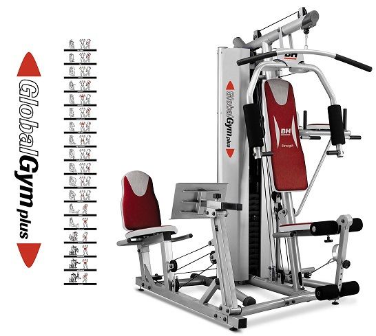
KG Letter Pounds
8 A 18
16 B 36
25 C 55
33 D 75
42 E 95
50 F 110
59 G 130
67 H 150
75 I 165
85 J 190
100 K 220
27Fig.29 Fig.30
Fig.31
28Español
INSTRUCCIONES DE
SEGURIDAD.- RIESGO PARA LA SALUD
Este aparato ha sido diseñado y Precaución: Antes de comenzar a
construido de modo que proporcione utilizar el equipo, consulte a su
la máxima seguridad. Sin embargo, médico.
deben aplicarse ciertas precauciones Esta advertencia es especialmente
al utilizar aparatos de ejercicio. Lea el importante para personas de edades
manual en su totalidad antes de superiores a 35 años o con
montar y utilizar la máquina. problemas de salud.
1.-Si sufre mareos, náuseas, dolor en
Guarde estas instrucciones. el pecho o cualquier otro síntoma
USO durante la utilización de este aparato,
1.-Esta unidad está diseñada para uso PARE el ejercicio. ACUDA A UN
doméstico. No es apropiado para uso MÉDICO INMEDIATAMENTE
profesional o clínico. 2.- Trabaje en el nivel de ejercicio
2.- El peso de usuario no debe recomendado, no llegue al
exceder de 130 Kg. agotamiento. El uso incorrecto o el
3.- Este aparato ha sido probado y exceso de ejercicio repercute
cumple los requisitos de los estándares negativamente en su salud.
europeos EN ISO 20957-1 y EN957-2 3.- Antes de utilizar este aparato,
bajo la clase H.C. realice un calentamiento con
4.- Los padres y otras personas ejercicios de estiramiento.
responsables de los niños deben de
tener en cuenta la naturaleza curiosa INDICACIONES GENERALES
de estos y que puede llevarles a 1.- Retire todas las partes del cartón
situaciones y conductas que pueden de embalaje e identifíquelas con
resultar peligrosas. Esta unidad no ha respecto al listado, para asegurarse
de utilizarse en ningún caso como de que no falta ninguna. No elimine el
juguete. No los deje desatendidos en cartón hasta haber montado el equipo
la habitación en la que guarda el completamente.
aparato. 2.- Utilice el aparato siempre de
Las personas discapacitadas no acuerdo con las instrucciones. Si
deberán utilizar la máquina sin la encuentra algún componente
asistencia de una persona cualificada defectuoso durante el montaje o
o un médico. comprobación del aparato, o si oye
algún ruido extraño durante la
utilización, pare y contacte con el
servicio de asistencia técnica oficial.
No utilice este aparato hasta que se
haya solucionado el problema.
3.- Compruebe el equipo antes de
comenzar el ejercicio, para
29asegurarse de que se han montado técnica oficial si tiene dudas.
todas las piezas y que las tuercas,
tornillos, pedales y brazos se han INSTRUCCIONES PARA EL
apretado correctamente antes del uso. EJERCICIO.-
4.- Utilice sólo componentes originales El uso del EQUIPO le reportará
del fabricante. El uso de otros diferentes beneficios, mejorará su
componentes o modificaciones en la condición física, tono muscular y,
máquina invalida la garantía. junto con una dieta baja en calorías, le
5.- Utilice el aparato sobre una ayudará a perder peso.
superficie sólida y a nivel. NO utilice el
equipo cerca del agua o al aire libre. 1 La fase de calentamiento.
6.- Por razones de seguridad, el
equipo deberá disponer a su Esta fase acelera la circulación
alrededor de un espacio libre no sanguínea en el cuerpo y pone a tono
inferior a 1 m. No coloque objetos los músculos para el ejercicio.
cortantes alrededor de la máquina. También reduce el riesgo de
7 Utilice este aparato sólo para los calambres y lesiones musculares. Es
fines descritos en este manual. NO aconsejable realizar algunos ejercicios
utilice accesorios no recomendados de estiramiento, según se muestra
por el fabricante. más adelante.
8.- Mantenga las manos alejadas de
las partes en movimiento.
9.-Utilice una indumentaria adecuada
para la realización de ejercicio. No
use prendas holgadas que podrían
engancharse en el equipo. Utilice
siempre calzado para correr o para
aerobic cuando utilice la máquina.
Átese los cordones correctamente. Realice cada estiramiento
10.- Es responsabilidad del propietario aproximadamente durante 30
asegurarse que todos los usuarios de segundos, no fuerce los músculos. Si
la máquina estén adecuados e siente dolor, PARE.
informados sobre todas las
precauciones necesarias. Su unidad 2. La fase de ejercicio.
sólo puede ser usada por una persona En esta fase se realiza el esfuerzo
al mismo tiempo. más importante. Tras el ejercicio
11.- Revise periódicamente los regular, los músculos de las piernas
elementos de la máquina como polea, aumentarán su flexibilidad.
cable etc. Compruebe si existen Es muy importante mantener un ritmo
daños y en caso de que los hubiera constante. El ritmo de ejercicio será lo
debe cambiarlo de inmediato. Revise bastante alto para aumentar las
periódicamente el apriete de los pulsaciones hasta la zona objetivo
tornillos y reapriételos si es necesario. que se muestra en el gráfico
Compruebe ruidos extraños y siguiente.
contacte con el servicio de asistencia
30mayor esfuerzo. Deberá reducir la
velocidad para mantener el ritmo
cardíaco en la zona objetivo.
INSTRUCCIONES DE
MONTAJE.-
Saque la unidad de la caja y
Esta fase debería durar un mínimo de compruebe que tiene todas las piezas.
12 minutos aunque se recomienda a Para el montaje de esta máquina,
la mayoría de la gente comenzar con se recomienda la ayuda de una
períodos de 10-15 minutos. segunda persona.
Fig.1.-
3. La fase de relajación (1) Cuerpo superior.
Esta fase permite la relajación del (2) Tubo base.
sistema cardiovascular y muscular. Se (3) Tubo asentamiento exterior
trata de una repetición de los derecho.
ejercicios de calentamiento, por (4) Tubo asentamiento exterior
ejemplo, reduciendo el ritmo, y izquierdo.
continuando aproximadamente 5 (5) Cuerpo principal.
minutos. Repita los ejercicios de (6) Mástil vertical.
estiramiento, y recuerde no forzar los (7) Soporte trasero.
músculos. (8) Soporte cruzado.
Según transcurran los días, necesitará (9) Soporte Glúteos.
entrenamiento más prolongados y de (10) Soporte delantero.
mayor intensidad. Es recomendable (11) Tubo trasero empujador.
ejercitarse un mínimo de tres días por (12) Tubo delantero empujador.
semana, en días alternos. (13) Soporte empujador.
(15) Soporte empujador glúteos.
Tonificación muscular. (16) Agarradero derecho de asiento.
Para tonificar los músculos durante el (17) Agarradero izquierdo de asiento.
ejercicio deberá seleccionar una (18) Soporte giro brazos Butterfly.
resistencia alta. Esto implicará una (19) Chapa de tope brazos.
mayor tensión sobre la musculatura
de las piernas y brazos y quizás deba Fig.2
reducir el tiempo del ejercicio. Si (26) Puños del “Butterfly”.
también desea mejorar su forma física (27) Barra de ejercicios larga.
general, deberá cambiar su programa (28) Barra de ejercicios corta.
de entrenamiento. Realice los (29) Soporte asiento.
ejercicios de calentamiento y (32) Soporte manos asiento.
relajación de costumbre, pero cuando (33) Soporte abdominales.
esté llegando al final de la fase de (34-35) Soportes inferiores de brazos.
ejercicio, aumente la resistencia para (36-37) Brazos de abdominales.
someter sus piernas y brazos a un (38) Columnas de pesas.
31Fig.3 (101) Tornillo c/avellanada M-10x25.
(39) Tubo selector de pesas. (102) Tornillo M-10x25.
(42) Pesa superior. (103) Tornillo M-10x35.
(43) Conjunto de pesas. (104) Tornillo M-10x50.
(44) Selector de pesas. (105) Tornillo M-10x60.
(45) Pasador primera pesa. (106) Tornillo M-10x65.
(46) Casquillo sujeción primera pesa. (107) Tornillo M-10x70.
(54) Pomo apriete soporte piernas. (108) Tornillo M-10x75.
(60) Enganche de cadenas. (109) Tornillo M-10x80.
(61) Cadena cable pesas. (110) Tornillo M-10x85.
(62) Cadena cable tiro piernas. (111) Tornillo M-10x95.
(68) Pasador seguridad piernas. (112) Tornillo M-10x100.
(70) Selector de ejercicio “Butterfly”. (113) Tornillo M-10x105.
(71) Pasador de seguridad asiento. (114) Tornillo M-12x75.
(73) Tapón tuerca de M12. (115) Tornillo M-12x135.
(75) Arandela inferior de pesas.
(76) Tope inferior de pesas. Fig.6
(80) Tubo superior piernas. (117) Arandelas planas M-5.
(87) Asiento glúteos. (118) Arandelas planas M-8.
(88) Asiento. (119) Arandelas planas M-10.
(89) Tapizado respaldo glúteos. (120) Arandelas curvadas M-10.
(90) Respaldo. (121) Arandelas planas M-12.
(91) Tapizados de apoyabrazos. (122) Arandelas planas 40x19,5.
(92) Respaldo de abdominales. (123) Arandelas planas 46x26.
(93) Espumas largas. (124) Arandelas planas 32x13.
(94) Espumas inferiores soporte (125) Tuerca autoblocante de M-10.
piernas. (126) Tuerca autoblocante de M-12.
(136) Pomo apriete soporte asiento. (130) Arandelas curvadas M-8.
Fig.4 MONTAJE.-
(95)Carcasa lateral delantera derecha. 1.-Coloque el cuerpo principal (5) en
(96)Carcasa lateral delantera izquierda. la posición vertical como le muestra la
(127) Tapa superior. Fig.7.
(128) Soporte de carcasas.
(129) Cinta agarradero de pie. 2.-Coloque las bases (3 y 4) en el
(131) Espumas superiores soporte cuerpo principal (5) tal como indica la
piernas. Fig.7, haciendo coincidir las etiquetas
(133) Soporte malla trasera. autoadhesivas izquierda y derecha,
(134) Malla protección trasera. apretando suavemente los tornillos
(111).
Fig.5 (TORNILLERÍA)
(97) Tornillo cabeza destornillador M- 3.-Coloque la pata de soporte (2)
5x10. apretando fuertemente todos los
(98) Tornillo c/Allen M-8x16. tornillos (112) con la contra placa
(99) Tornillo M-8x20. trasera Fig.8.
(100) Tornillo M-8x58.
324.-Coloque el cuerpo principal (6) en la MONTAJE DEL SOPORTE
base tal como indica la Fig.8. Coloque BRAZOS BUTTERFLY.-
los tornillos (112) y la placa, solamente 8.-Coloque el soporte de brazos
apuntando sin apretar Fig.8. Preste Butterfly (18) en el soporte superior
atención a la posición vertical de la (1) Fig.12. Introduzca el tornillo (115)
estructura principal (5) Fig.8. junto con las arandelas (121) y la
tuerca (126) y apriete.
5.-Coloque el cuerpo superior (1) Fig.9 Coloque el tapón embellecedor de
en el cuerpo principal (5) metiendo la tuerca (73).
punta del cable por el agujero (M).
Apriete ligeramente las tuercas (125) MONTAJE CHAPA TOPE DE
tal como se indica en la Fig.9. BRAZOS.-
NOTA: Una vez realizado este paso 9.-Suelte las tuercas junto con las
del presente montaje, se tienen que arandelas y los tornillos del soporte
reapretar fuertemente los tornillos giro de brazos Fig.12.
montados en los pasos anteriores. A continuación coloque la chapa (19)
con el logo hacia fuera, y monte los
MONTAJE SOPORTE DE tornillos junto con las arandelas y
ABDOMINALES.- tuercas, que ha soltado anteriormente.
6.-Coja el soporte de abdominales (33) Apriete fuerte los tornillos.
y atorníllelo al soporte principal (5) con
MONTAJE DE ESPUMAS
los tornillos (111) y arandelas (120) en
la parte superior, como la inferior con SUPERIORES.-
los tornillos (109) y arandelas (120) 10.-Coja las espumas (93) e
mostradas en la Fig.10. introdúzcalas en los dos tubos del
Suelte los tornillos del soporte delantero ejercicio de “BUTERFLY” según le
(10) Fig.10. Coloque la pata de soporte muestra la Fig.12.
delantero (10) apretando suave, sin Continuación coja la maneta (26),
tensar del todo los tornillos (102), junto suelte el tornillo junto con la arandela
con las arandelas (120) Fig.10. Fig.12 y atornille en los brazos (20),
derecho y (21) izquierdo.
MONTAJE DE BRAZOS
MONTAJE ESTRUCTURA
ABDOMINALES.-
7.-Una vez montado el soporte (33) en ASIENTO.-
el paso 6 del presente manual, coja 11.- Coja el pomo del soporte asiento
los tubos (34-35) y atornille los (136). Posicione en uno de los dos
tornillos (106) sin apretar al soporte agujeros de altura Fig.13 del asiento y
(33) Fig.11. atornille con el pomo (136).
Coloque el pasador de seguridad (71).
A continuación coja los brazos (36-37)
y encájelos en dirección de la flecha
Fig.11, en los tubos (34-35), monte los
tornillos y atornille fuertemente
también los tornillos (106) que se
habían dejado solo tensados.
33MONTAJE AGARRADERO MONTAJE AGARRADERO
ASIENTO.- ASIENTO.-
12.-Introduzca por la parte inferior del 16.-Posiciones los agarraderos (16) y
soporte del asiento el agarradero (32) (17) en el soporte de glúteos (9)
Fig.13. Fig.17. Sujételo con los tornillos (110)
Sujételo con los tornillos (108) las las arandelas (119) y las tuercas
arandelas (119) y las tuercas (125). (125).
MONTAJE DEL ASIENTO.- MONTAJE DEL ASIENTO
13 -Coja el asiento (88) y posiciónelo GLÚTEOS.-
en el soporte asiento Fig.13. 17.-Coja el asiento (87) y posiciónelo
Coja los tornillos (99) y las arandelas en el soporte asiento Fig.17.
(118) y atorníllelo. Coja los tornillos (99) y las arandelas
(118) y atorníllelo.
MONTAJE DE ESPUMAS
INFERIORES.- MONTAJE TUBOS
14.-En primer lugar coja las espumas EMPUJADORES.-
(131) e introdúzcalas en los tubos 18.- Posicione el tubo empujador (11)
redondos superiores del soporte de sobre la “U” del soporte glúteos (9)
piernas, Fig.14. Fig.18, alineando los agujeros
A continuación realice el mismo proceso introduzca el tornillo (116), coloque las
de montaje para las espumas inferiores arandelas (121) y apriete con las
(94) del soporte de piernas (40). tuercas (126), coloque el tapón
protector (73).
MONTAJE ACCESORIO Seguido realice el mismo proceso de
GLÚTEOS.- montaje para el tubo empujador (12)
15.- Posicione el soporte trasero (7) Fig.18.
seguido, coloque el soporte cruzado (8)
y atorníllelo al tubo de asentamiento MONTAJE EMPUJADOR DE
exterior (3 y 4) Fig.15 y monte los GLÚTEOS.-
tornillos (109) junto con las arandelas 19.-Posicione el soporte empujador de
(120) y las tuercas (125). glúteos (14), como le muestra la
A continuación coja el soporte de Fig.19. Alinee los agujeros sobre los
glúteos (9) Fig.16 y atorníllelo a los tubos empujadores e introduzca el
soportes (7) y (8) con los tornillos tornillo (116) junto con las arandelas
(110) las arandelas (119) y las tuercas (121) y las tuercas (126), apriete
(125) Fig.16. fuertemente.Coloque los tapones
embellecedores (73).Coja el
NOTA: Una vez realizado este paso empujador (15) e introdúzcalo en
del presente montaje, se tienen que dirección de la flecha en el soporte de
reapretar fuertemente los tornillos glúteos, coloque el tornillo (105), las
montados en los pasos anteriores. arandelas (119) y las tuercas (125) y
apriete fuertemente. Regule a su
medida y apriete el pomo (119) en el
sentido de las agujas del reloj.
34MONTAJE CABLE GLÚTEOS.- izquierda y derecha (95 y 96) en el
20.-Pase un extremo del cable (66) cuerpo principal (5) haciendo coincidir el
Fig.19, que sale de la polea D1 por las perno de la carcasa en la base y
poleas E1 y F1, coja el mosquetón después apretando ligeramente los
(60) y sujételo al tubo empujador (12) tornillos en la parte superior Fig.22.
Fig.19.
El otro extremo del cable (66), páselo Fije también estas carcasas en los
por la polea B1 y A1 y sujételo con el tubos laterales de la máquina, con los
mosquetón (60) al tubo transversal (8) tornillos (98) Fig.22.
Fig.19.
MONTAJE DE LAS PESAS.-
MONTAJE DEL RESPALDO.- 26.-Coloque los tubos de guía (38)
21.-Coja el respaldo (90), y acérquelo al junto con las arandelas (75) y los
mástil central (6), como muestra la topes inferiores de pesas (76), en la
Fig.20. posición tal como indica la Fig.23.
A continuación coja los tornillos (99)
las arandelas (118) y atornille el 27.-A continuación coloque las pesas
respaldo Fig.20. (43) en los tubos de guía tal como
indica la Fig.23, respetando el orden
MONTAJE RESPALDO alfabético y con las letras giradas
GLÚTEOS.- frente a la máquina, comenzando por
22.-Coja el respaldo (89), y acérquelo la letra (L).
al mástil central como muestra la
28.-Seguido coja el tubo selector de
Fig.20.
pesas (44) Fig.23 y monte el casquillo
A continuación coja los tornillos (99)
de sujeción (46) de la primera pesa e
las arandelas (118) y atornille el
introduzca el pasador (45). Coloque la
respaldo Fig.20.
última pesa (43) en las barras (38).
MONTAJE RESPALDO.- Colocando los casquillos (69), apriete
23-Coja el respaldo (92), y acérquelo los tornillos (106) del tubo de guía (38)
al mástil central como muestra la al cuerpo principal (5) tal como
Fig.21. muestra la Fig.23.
A continuación coja los tornillos (99)
MONTAJE DEL SISTEMA DE
las arandelas (118) y atornille el
respaldo Fig.21. CABLES.-
29.-En primer lugar compruebe que los
MONTAJE DE TAPIZADOS DE cables de acero estén correctamente
APOYO.- colocados en las poleas que vienen
24.-Coja los tapizados (91) y apóyelos premontadas siguiendo las flechas
en los brazos de abdominales Fig.21. situadas en la Fig.24.
Coja los tornillos (100) y las arandelas
(130) y atornille.
En el paso anterior del montaje de
las pesas, estas ya están colocadas
MONTAJE DE LAS CARCASAS.- en su alojamiento.
25.-Coloque las carcasas de protección Levante la primera pesa (42) y
coloque el tubo selector de pesas (39)
35tal como muestra la Fig.24A. 30.-Introduzca la cadena (62) en el
Enrosque el tornillo (63) en el tubo gancho del accesorio de piernas (41)
selector (39), cuando esté enroscado, Fig.24 para poder realizar el ejercicio
baje la pesa hasta apoyarla en las de piernas.
otras pesas.
31.-Acople la carcasa superior (127)
Introduzca el pasador selector de pasando por el cuerpo superior (1)
pesas (44) el tubo selector (39) Fig.23 hasta encajar en el cuerpo principal
y apriete la tuerca (U) fuertemente (5) Fig.25.
Fig.24A. Coloque los tornillos (97).
A continuación sujete un extremo 32.-Coloque el selector (70) tal como
del cable (65). en la pletina del brazo muestra la Fig.25 para poder realizar
izquierdo del ejercicio “Butterfly” el ejercicio “Butterfly”.
Fig.24B, coloque el tornillo (103) con
las arandelas (119) y la tuerca (125).
MONTAJE PROTECCIÓN
Realice similar montaje con el otro TRASERA.-
extremo del cable (65) del brazo 32A.-Posicione las sujeciones (133)
derecho del ejercicio del Butterfly. en la malla (134) como le indica la
Fig.25A.
Monte las chapas (59) sobre las A continuación posicione las
poleas (56) de la Fig.24C. sujeciones (133) sobre el cuerpo
principal (5), coloque los tornillos (98),
Coja el extremo del cable inferior junto con las arandelas (118) y
tiro de pies (64) y siguiendo las atornille como le muestra la Fig.25A.
flechas indicadas en el cable de la
Fig.24, páselo por la primera polea COLOCACIÓN DE LA VARILLA
(A1), como se le ilustra en la Fig.24. SELECTORA DE PESAS.-
Seguido pase la misma punta por la 33.-Introduzca la varilla selectora de
polea (B1; C1) inferior Fig.24. pesas (44) en el orificio de las pesas
Continúe pasando la punta del cable adecuado para su ejercicio, tal como
(64) por la tercera polea (D1) Fig.24. muestra la Fig.26.
Sujete el extremo del cable al
mosquetón (60) y a la cadena (61), 34.-Cuando la apertura de la varilla
posiciónela en el extremo unida al pase el orificio del tubo selector de
soporte del tubo base Fig.24. pesas (39), gire la varilla selectora
(44) en el sentido contrario a las
Nota: Al transcurrir un tiempo, es agujas del reloj, quedando la varilla tal
posible que note una ligera distensión como muestra la Fig.27. Asegúrese y
del cable de acero, por el compruebe que el selector esté bien
asentamiento del cable. colocado y que no salga del tubo
Para solucionarlo, basta con tensar el selector de pesas. Para retirar la
cable de acero cambiando de eslabón varilla, gírela en el sentido de las
de la cadena (61). agujas del reloj y tire de ella.
Para un mejor control del ejercicio, las
pesas están marcadas con letras.
36Consultando las tablas de NIVELADO.-
equivalencia Fig.28, pegadas en la 36.-Una vez colocada su unidad en el
base de la máquina, sabrá los lugar definitivo, compruebe que el
esfuerzos ejercidos con cada letra en asentamiento en el suelo y su
Kg y libras. nivelado sean correctos. Esto se
consigue roscando más o menos las
DOBLADO DEL ASIENTO.- patas regulables (79). Fig.30.
35.-Para doblar el asiento, retire la
varilla de seguridad (71) y levante el Para cualquier consulta, no dude en
asiento en el sentido de la flecha, tal ponerse en contacto con el
como indica la Fig.29 y vuelva a fijar (S.A.T).Servicio de Asistencia
el asiento con la misma varilla. Técnica, llamando al teléfono de
atención al cliente (ver página final del
Nota: El asiento puede graduarse en presente manual).
altura, disponiendo de dos posiciones.
BH SE RESERVA EL DERECHO A
MODIFICAR LAS ESPECIFICACIONES
DE SUS PRODUCTOS SIN PREVIO
AVISO.
37English
SAFETY INSTRUCTIONS.- HEALTH HAZARDS
This appliance has been designed and Caution: Consult your doctor
constructed to provide maximum before beginning to use the
safety. Nevertheless, certain equipment. This advice is
precautions should be taken when especially important for those over
using exercise equipment. Carefully 35 or suffering from health
read through the instructions problems.
contained in this manual. It provides 1.If you experience dizziness, nausea,
you with important information about chest pains or any other symptom
assembly, safety and use of the while using this appliance STOP the
machine. exercise. SEEK MEDICAL
ATTENTION IMMEDIATELY.
Keep these instructions safe for 2. Work at the recommended exercise
future use. level, do not overexert yourself.
Incorrect or excessive exercising can
USE endanger your health.
1. This unit has been designed for 3. Do warm up stretching exercises
home use. It is not suitable for before using the equipment
commercial or therapeutic use.
2. The user weight does not have to GENERAL INSTRUCTIONS
exceed 130kg 1. Remove all the parts from the
3. This appliance has been tested and cardboard packaging and check them
it complies with standard EN ISO against the parts list to ensure that there
20957-1 and EN957-2 under class is nothing missing. Do not throw the
H.C. cardboard away until the elliptical trainer
4. Parents and/or those responsible is fully assembled.
for children should always take their 2. Always use the appliance in
curious nature into account and how accordance with the instructions. If you
this can often lead to hazardous discover any defective component while
situations and behaviour resulting in assembling or checking the equipment,
accidents. This unit does not have to or if you hear any strange noise during
be used in any case like toy. DO NOT exercise then stop and contact
leave them unsupervised in the room customer care service. Do not use the
where this machine is kept. appliance until the problem has been
Disabled people should not use the solved.
machine without the assistance of a 3. Check the equipment trainer before
qualified person or a doctor. starting the exercise; to make sure that
all of the parts are attached and that the
nuts, bolts, pedals and focus bars have
been tightened correctly prior to use.
384. Use original spares from supplier. 1,Warm-up phase
The replacement or modification of This phase speeds up the body’s blood
any component, other than what is circulation and gets the muscles ready
approved by supplier, will void your of for exercise. It also reduces the risk of
warranty. cramp and sprains. It is advisable to do
5. Use the appliance on a level, solid some stretching exercises, as shown
surface. DO NOT use the appliance below. Each stretch should last
outdoors or close to water. approximately 30 seconds, do not
6. In the interest of safety, the overexert the muscles. If you feel pain,
equipment must have at least 1 metre of STOP.
free space around it. Do not place
sharp objects near the machine.
7 This appliance must only be used for
the purposes described in this manual.
DO NOT use accessories that are not
recommended by the manufacturer.
8 Keep your hands well away from
any of the moving parts.
9 Wear clothing suitable for doing 2. Exercise phase
exercise. Do not use baggy clothing This phase requires the greatest
that might get caught up in the bicycle. physical exertion. After regular
Always wear running shoes or trainers exercise the leg and arms muscles will
when using the machine. Make sure become more flexible. It is important
all laces/cords are tied correctly. to keep the rhythm constant. The
10 The owner is responsible for rhythm of the exercise should be fast
ensuring that anyone who uses the enough to bring the heart rate into the
machine is duly informed about the target area, as shown on the following
necessary precautions. graph:
11. Periodically check the parts of the
machine such as pulley, cable etc.
Check for damage and if one exists
should change it right away.
Check at regular intervals whether all
screw connections are tight, and
retighten them as required. Check
regularly for damage and wear and
contact customer care if any doubt.
This phase should last at least 12
EXERCISE INSTRUCTIONS.- minutes, although it is advisable for
Use of the EQUIPMENT TRAINER most people to start off with sessions
offers various benefits; it will improve of 10-15 minutes.
fitness, muscle tone and when used in
conjunction with a calorie controlled diet
it will help you to lose weight.
393. Cool-down phase (6) Vertical mast.
This phase allows the cardiovascular (7) Rear support.
and muscle system to relax. It consists (8) Cross support.
of repeating the warm-up exercises, (9) Gluteal support.
i.e. reducing the rhythm and (10) Front support.
continuing for approximately 5 (11) Rear push bar.
minutes. Repeat the stretching (12) Front push bar.
exercises but remember not to (13) Push bar support.
overexert the muscles. (15) Gluteal push bar support.
(16) Right seat handgrip.
Eventually your training sessions will
(17) Left seat handgrip.
have to become longer and more
(18) “Butterfly” arm rotation support.
intensive. It is advisable to exercise at
(19) Arm limit plate.
least three days per week, on
alternate days. Fig.2
(26) Butterfly bars.
Muscle toning (27) Long exercise bar.
You should select a high exertion level (28) Short exercise bar.
in order to tone muscles during (29) Seat support.
exercise. This entails greater stress on (32) Seat hand support.
the leg and arm muscles, so it may be (33) Abdominal support.
wise to reduce exercise times. If you (34-35) Bottom arm supports.
also wish to improve your overall (36-37) Abdominal arms.
fitness then you should change your (38) Weight columns.
training program. Do the warm-up and
cool-down exercises as normal but Fig.3
when you are reaching the end of the (39) Weight selector post.
exercise phase, increase the exertion (42) Top weight.
level in order to make your legs work (43) Weight set.
harder. You should reduce speed in (44) Weight selector.
order to keep your heart rate within (45) First weight lockpin.
the target area. (46) First weight holding collar.
(54) Leg support adjustment knob.
1. ASSEMBLY INSTRUCTIONS.-
(60) Chain hook.
Take the unit out of its box and make
(61) Weight cable chain.
sure that all of the pieces are there:
(62) Leg pull-up cable chain.
The assistance of a second person
(68) Leg lock pin.
is required for assembling this
(70) Butterfly exercise selector.
machine.
(71) Seat locking pin.
Fig.1; Box 1.- (73) M-12 nut cover.
(1) Top body. (75) Bottom washer for weights.
(2) Main post. (76) Bottom stop for weights.
(3) Outer right stabiliser. (80) Top leg bar.
(4) Outer left stabiliser. (87) Gluteal seat
(5) Main body. (88) Seat.
(89) Gluteal backrest covering.
40(90) Backrest. (124) Flat washers 32x13.
(91) Armrest covering. (125) Self locking M-10.
(92) Abdominal support. (126) Self locking M-12.
(93) Long foam covers. (130) Washers M-8.
(94) Bottom leg support foam cover.
(136) Seat support adjustment knob. ASSEMBLY.-
1.-Place the main body (5) in the
Fig.4 upright position, as shown in Fig.7.
(95) Front right side panel.
(96) Front left side panel. 2.-Place the bases (3-4) onto the main
(127) Top cover. body (5), as shown in Fig.7, ensuring
(128) Casing bracket. the stickers on the left and right match
(129) Ankle strap. up, and tighten the screws (111).
(131) Top leg support foam cover.
(133) Mesh bracket 3.-Fit the support leg (2) tightening the
(134) Mesh bolts (112) against the rear plate Fig.8.
Fig.5 (NUTS & BOLTS) 4.-Put the screws (112) into the screw
(97) Slot head bolt M-5x10. holes so that they are in their correct
(98) Allen screw M-8x16´. position, without tightening Fig.8.
(99) Bolts M-8x20. Make sure the main structure (5)
(100) Bolts M-8x58. remains in a vertical position Fig.8.
(101) Countersunk screw M-10x25.
(102) Bolts M-10x25. 5.-Fit the top body (1) Fig.9 onto the
(103) Bolts M-10x35. main body (5). inserting the tip of the
(104) Bolts M-10x50. cable through the hole (M).Hand tighten
(105) Bolts M-10x60. the nuts (125) as shown in Fig.9.
(106) Bolts M-10x65. NOTE: Once this stage of the assembly
(107) Bolts M-10x70. has been completed, all of the bolts
(108) Bolts M-10x75. fitted should be retightened securely.
(109) Bolts M-10x80.
(110) Bolts M-10x85. FITTING THE ABDOMINAL
(111) Bolts M-10x95. SUPPORT.-
(112) Bolts M-10x100. 6.-Take the abdominal support (33)
(113) Bolts M-10x105. and bolt it onto the main support (5),
(114) Bolts M-12x75. using bolts (111) and washers (120) at
(115) Bolts M-12x135. the top and the bolts (109) and
washers (120), as shown in Fig.10.
Fig.6 Remove the bolts from the front
(117) Flat washers M-5. support (10), Fig.10. Fit the front
(118) Flat washers M-8. support leg (10) but only
(119) Flat washers M-10. handtightening all of the bolts (102)
(120) Washers M-10. along with their washers (120), Fig.10.
(121) Flat washers M-12.
(122) Flat washers 40x19,5.
(123) Flat washers 46x26.
41FITTING THE ABDOMINAL FITTING THE SEAT HANDGRIP.-
ARMS.- 12.- Insert the handgrip (32) through
7.-Once the support (33) in step 6 of the lower part of the seat support,
these instructions has been fitted, take Fig.13. Attach using bolts (108),
hold of the tubes (34-35) and washers (119) and nuts (125).
handtighten the bolts (106) onto the
support (33), Fig.11. FITTING THE SEAT.-
Next, take ther arms (36-37) and slot 13.-Take the seat (88) and position it
them onto the tubes (34-35) in the on the seat support Fig.13.
direction of the arrow, Fig.11, fit the Fit the bolts (99) with their washers
bolts and tighten securely, as well as (118) and tighten securely.
bolts (106) that were left handtight.
FITTING THE BOTTOM FOAM
FITTING THE BUTTERFLY ARM COVERS.-
SUPPORT.- 14.-First take the foam covers (131)
8.- Fit the butterfly arm support (18) and fit them onto the top rounded
into the top support (1), Fig.12. Insert tubes for the leg support Fig.14.
bolt (115), along with washer (121) Now do the same for the bottom leg
and nut (126), and tighten securely. Fit support foam covers (94).
the nut cap (73).
FITTING THE GLUTEAL
FITTING THE ARM LIMIT PLATE.- ACCESSORY.-
9.-Take the nuts, washers and bolts 15.- Position the rear support (7), next
off the arm rotation support Fig.12. fit the cross support (8) and screw it
Next, fit the plate (19) with the logo on to the outer seat frame (3 and 4),
facing outward and refit the bolts, Fig.15. Fit bolts (109) along with
washers and nut. Tighten the bolts washers (120) and nuts (125).
securely. Now take the gluteal support (9),
FITTING THE TOP FOAM COVERS.- Fig.16, and attach it to the supports
10.-Take the foam covers (93) and fit (7) and (8) using bolts (110), washers
them onto the two BUTTERFLY bars, (119) and nuts (125) Fig.16.
as shown in Fig.12.
Now take the handle (26), remove the NOTE: Once this stage of the
bolt and the washer Fig.12 and screw it assembly has been completed, all of
on to the arms (20) right and (21) left. the bolts fitted previously should be
retightened securely.
FITTING THE SEAT STRUCTURE.-
11.- Take the knob from the seat FITTING THE SEAT HANDGRIP.-
support (136). Position it on one of the 16.– Position the handgrips (16) and
two seat height setting holes Fig.13 (17) on the gluteal support (9), Fig.17.
and secure using the knob. Attach using bolts (110), washers
Fit the seat locking pin (71). (119) and nuts (125).
42FITTING THE GLUTEAL SEAT.- Now use the bolts (99) and washers
17.-Take the seat (87) and position it (118) to secure the backrest Fig.20.
on the seat support, Fig.17.
Fit the bolts (99) with their washers FITTING THE GLUTEAL
(118) and tighten securely. BACKREST.-
FITTING THE PUSH BARS.- 22.-Take the backrest (89) and
18.- Position the push bar (11) on the position it against the central mast, as
“U” bracket for the gluteal support (9), shown in Fig.20.
Fig.18, align the holes and insert Now use the bolts (99) and washers
screws (116), fit washers (121) and (118) to secure the backrest, Fig.20.
tighten using nuts (126). Now fit the
screw caps (73). FITTING THE BACKREST.-
Go through the same procedure for 23.-Take the backrest (92) and
push bar (12), Fig.18. position it against the central mast, as
shown in Fig.21.
FITTING THE GLUTEAL PUSH BAR.- Now use the bolts (99) and washers
19.- Position the gluteal push bar (118) to secure the backrest, Fig.21.
support (14) as shown in Fig.19.
Align the holes on the push bars and FITTING THE SUPPORT
insert bolts (116) along with the COVERINGS.-
washers (121) and nuts (126), tighten 24.-Take the coverings (91) and position
securely. Fit the screw caps (73). them on the abdominal arms, Fig.21.
Take push bar (15) and insert it Fit the bolts (100) with their washers
through the gluteal support in the (130) and tighten securely.
direction of the arrow, fit bolts (105),
washers (119), and nuts (125) and FITTING THE PANELS.-
tighten securely. Adjust to suit and 25.-Position the left and right
tighten it by turning the control knob protection plates (95 and 96) onto the
(119) clockwise. main frame (5), fitting the plate wedge
into the accommodating groove in the
FITTING THE GLUTEAL CABLE.- base, then tighten screws (98) slightly
20.- Pass one end of cable (66), in the upper part as shown in Fig.22.
Fig.19, coming out of pulley D1,
FITTING THE WEIGHTS.-
through pulleys E1 and F1, take the
26.- Fit the guide post (38) along with
carabiner (60) and attach it to push
washers (75) and the bottom weight
bar (12), Fig.19.
stops (76) as shown in Fig.23.
Pass the other end of cable (66)
through pulley B1 and A1 and use 27.- Next, place the weights (43), onto
carabiner (60) to attach it to the the guide post as shown in Fig.23, in
crossbar (8), Fig.19. correct alphabetical order with the
letters facing the front of the machine,
FITTING THE BACKREST.- beginning with the letter “L”.
21.-Take the backrest (90) and
position it against the central mast, as
shown in Fig.20.
4328.- Now take the weight selector tube cable (64) through the third pulley (D1)
(44), Fig.23, and attach the holding Fig.24. Attach the end of the cable to
collar (46) for the first weight and the carabiner (60) and to chain (61),
insert the lockpin (45). Fit the last position it on the end joined to the
weight (43) onto the bars (38). support on the base, Fig.24.
Fit the bushes (69) tighten the bolts
(106) for the guide post (38) to the Note: After a while you may notice
main body (5), as shown in Fig.23. that steel cable slackens a little due to
the cable settling into position.
FITTING THE CABLE SYSTEM.- To remedy this just tension the steel
29.- First check that the steel cables cable by changing the chain link (61).
are correctly fitted into the pulleys that 30.- Fit the chain (62) onto the leg
are supplied prefitted, following the accessory hook (41) Fig.24, to be able
arrows in Fig.13. to do the leg exercises.
The weights have already been 31.- Attach the top casing (127) fitting
fitted into their housing in the previous it over the upper body (1) so that it
assembly step. slots onto the main body (5) Fig.25.
Lift the first weight (42) and fit the Fasten on using screws (97).
weight selector post (39), as shown in 32.- Set the selector (70) as shown in
Fig.24A. Fig.25 to be able to do the Butterfly
Screw bolt (63) into the selector exercise.
post (39), when it is screwed in, lower
the weight so that it rests on the other REAR PROTECTION ASSEMBLY.-
weights. 32A.-Place the fixing points (133) in
Insert the weight selector pin (44) the mesh (134) as shown in Fig.25A.
into the selector post (39), Fig.23, and Then, position the fixing points (133)
tighten nut (U) securely, Fig.24A. on the main body (5), place the
Next, attach one end of cable (65) screws (98), with washers (118) and
to the left arm plate for the Butterfly tighten, as shown in Fig.25A.
exercise, Fig.24B, fit bolt (103) with
washers (119) and nut (125). POSITIONING THE WEIGHT
Do the same with the other end of SEECTOR ROD.-
cable (65) for the right Butterfly 33.-Insert the weight selector (44) rod
exercise arm. into the orifice of the weights required
for the exercise, as shown in Fig.26.
Fit the plates (59) onto the pulleys
(56) as shownh in Fig.24C. 34.-When the rod notch has been fed
Take the end of the foot pull-up through the weight selector tube (39),
cable (64) and by following the arrows turn the selector rod anticlockwise, so
marked on the cable, Fig.24, pass it that the rod is held into place as
through the first pulley (A1), as shown shown in Fig.27. Check that the
in Fig.24. selector is firmly in position and that it
Next, pass the same tip through does not protrude from the weight
lower pulley (B1; C1) Fig.24. selector. To remove the rod, turn it
Continue passing the tip of the clockwise and pull.
44For optimum control of exercise LEVELLING.-
conditions, the weights are already 36.-Once it has been firmly positioned
marked with letters. By checking the into place, check the base and ground
equivalence charts on the bottom of level of the machine. Levelling can be
the apparatus, you will be able to improved by more or less swivelling
check the exercised strength as the the adjustable feet (79) Fig.30.
meaning of each letter Fig.28 is
expressed in kilograms and pounds. Do not hesitate to get touch with the
Technical Assistance Service if you
FOLDING THE SEAT.- have any queries by phoning customer
35.-To fold the seat, pull the safety rod services (see last page in manual)
(71) and lift it in the direction of the
arrow as shown in Fig.29. The same BH RESERVES THE RIGHT TO
rod is used to put the seat back up. MODIFY THE SPECIFICATIONS OF
Note: The seat can be put into two ITS PRODUCTS WITHOUT PRIOR
different positions. NOTICE
45G152X 46
Para pedido de repuesto: Indicar el código de la pieza y la cantidad
To order replacement parts: State the part code and Quantity
Ejemplo / E.g:
                        G152X001                              1

            Nº Code                Nº     Code           Nº    Code
             1  G152X001            46    G152X046        91   G152X091A
             2  G152X002            47    G152X047        92   G152X092A
             3  G152X003            48    G152X048        93   G152X093
             4  G152X004            49    G152X049        94   G152X094
             5  G152X005            50    G152X050        95   G152X095A
             6  G152X006            51    G152X051        96   G152X096A
             7  G152X007            52    G152X052        97   G152X097
             8  G152X008            53    G152X053        98   G152X098
             9  G152X009            54    G152X054        99   G152X099
            10  G152X010            55    G152X055       100   G152X100
            11  G152X011            56    G152X056       101   G152X101
            12  G152X012            57    G152X057       102   G152X102
            13  G152X013            58    G152X058       103   G152X103
            14  G152X014            59    G152X059       104   G152X104
            15  G152X015            60    G152X060       105   G152X105
            16  G152X016            61    G152X061       106   G152X106
            17  G152X017            62    G152X062       107   G152X107
            18 G152X018A            63    G152X063       108   G152X108
            19  G152X019            64    G152X064       109   G152X109
            20  G152X020            65    G152X065       110   G152X110
            21  G152X021            66    G152X066       111   G152X111
            22  G152X022            67    G152X067       112   G152X112
            23  G152X023            68    G152X068       113   G152X113
            24  G152X024            69    G152X069       114   G152X114
            25  G152X025            70    G152X070       115   G152X115
            26  G152X026            71    G152X071       116   G152X116
            27  G152X027            72    G152X072       117   G152X117
            28  G152X028            73    G152X073       118   G152X118
            29  G152X029            74    G152X074       119   G152X119
            30  G152X030            75    G152X075       120   G152X120
            31  G152X031            76    G152X076       121   G152X121
                                           47
32 G152X032 77 G152X077 122 G152X122
33 G152X033 78 G152X078 123 G152X123
34 G152X034 79 G152X079 124 G152X124
35 G152X035 80 G152X080 125 G152X125
36 G152X036 81 G152X081 126 G152X126
37 G152X037 82 G152X082 127 G152X127
38 G152X038 83 G152X083 128 G152X128
39 G152X039 84 G152X084 129 G152X129
40 G152X040 85 G152X085 130 G152X130
41 G152X041 86 G152X086 131 G152X131
42 G152X042 87 G152X087A 132 G152X132
43 G152X043 88 G152X088A 133 G152X133
44 G152X044 89 G152X089A 134 G152X134
45 G152X045 90 G152X090A 135 G152X135
48BH FITNESS SPAIN BH FITNESS PORTUGAL BH FITNESS UK
EXERCYCLE,S.L. MAQUINASPORT, APARELHOS Unit 12 Arlington Court
(Manufacturer) DE DESPORTO, S.A. Newcastle Staffs
P.O.BOX 195 Rua do Metalúrgico 465 ST5 6SS
01080 VITORIA (SPAIN) Zona Industrial Giesteira UK 0844 3353988
Tel.: +34 945 29 02 58 3750-325 Águeda (PORTUGAL) International
Fax: +34 945 29 00 49 Tel.: +351 234 729 510 00441782634703
e-mail: sat@bhfitness.com Fax: +351 234 729 519
www.bhfitness.com e-mail: info@bhfitness.pt AFTER SALES - UK
e-mail: service@bh-uk.co.uk
POST-VENTA BH SERVICE PORTUGAL
Tel: +34 945 292 012 / Tel.: +351 707 22 55 24
902 170 258 Fax: +351 234 729 519
Fax: +34 945 56 05 27 e-mail: info@bhfitness.pt
e-mail: sat@bhfitness.com
BH FITNESS NORTH AMERICA BH FITNESS MEXICO BH Germany GmbH
20155 Ellipse BH Exercycle de México S.A. de Altendorfer Str. 526
Foothill Ranch CV 45355 Essen
CA 92610 Eje 132 / 136 Tel: +49 201 450910-0
Tel: + 1 949 206 0330 Zona Industrial, 2A Secc. e-mail:
Toll free: +1 866 325 2339 78395 San Luis Potosí germany@bhfitness.com
Fax: +1 949 206 0013 S:L:P: MÉXICO Kostenfreie Telefonnummer:
e-mail: Tel.: +52 (444) 824 00 29 0800 0996655
fitness@bhnorthamerica.com Fax: +52 (444) 824 00 31 Ersatzteile:
www.bhnorthamerica.com www.bhlatam.com.mx www.homeactive.de
BH FITNESS ASIA BH FITNESS CHINA BH FITNESS FRANCE
No.139, Jhongshan Rd. BH China Co., Ltd.
Daya Township Block A, NO.68, Branch Lane SAV FRANCE
Taichung 428, Taiwan. R.O.C. 455, Lane 822, Tel : +33 0810 000 301
Tel.: +886 4 25609200 Zhen Nan RD., Li Zi Yuan, Fax : +33 0810 000 290
Fax: +886 4 25609280 Putuo, Shanghai 200331, P.R.C. savfrance@bhfitness.com
e-mail: info@bhasia.com.tw Tel: +86-021-5284 6694
Fax:+86-021-5284 6814
e-mail: info@i-bh.cn
BH SE RESERVA EL DERECHO A MODIFICAR LAS ESPECIFICACIONES DE SUS PRODUCTOS
SIN PREVIO AVISO.
SPECIFICATIONS MAY BE CHANGED WITHOUT PRIOR NOTICE DUE TO OUR PROGRAMME OF
CONTINUOUS PRODUCT DEVELOPMENT.
V6También puede leer