Instrucciones de Montaje - Mounting Instructions Instructions de Montage - Dirna Bergstrom
←
→
Transcripción del contenido de la página
Si su navegador no muestra la página correctamente, lea el contenido de la página a continuación
Instrucciones de Montaje   ES   Spanish

                                            Mounting Instructions     EN   English

                                           Instructions de Montage    FR   French

                                            Montageanweisungen        GE   German

                                            Istruzioni di Montaggio   IT   Italian
F-4218 rev.01

                Calidad en    Empresa
                Automoción    Registrada
                 IATF 16949    ISO 9001
                                                                       1002597509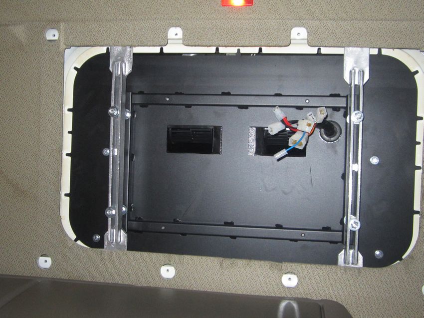
S
ES     INTEGRAL POWER II

                   Recomendaciones                                                       Herramientas
                    Para el montaje                                     Juego de Llaves Torx
                                                                        Juego de Llaves Allen
 • Antes de iniciar el montaje leer las instrucciones y                Llave fija 13
  seguirlas durante el proceso de instalacion.
                                                                        Tijeras
 • Usar las herramientas adecuadas para cada operación.               Flexómetro

                     Electricidad                                             Documentación relacionada
                                                                    Instrucciones de montaje                    1002597509
 • Desconectar la llave de contacto.                                Manual del usuario                          1002192411
 • Desconectar la batería antes de empezar el montaje.             Diagnosis de averías                        1002192414

 •
  Asegurar    el    conexionado    de   los     componentes         Listado de recambios                        1002597510
  eléctricos, verificando su correcto encaje.
                                                                                  Documentación incluida
                                                                    Guía rápida                                 1002455105
                      ! Atención                                    Garantía                                    220AA10017

Si durante el montaje el equipo se inclina o se abate                                      Simbología
la cabina con el equipo montado, se deberá esperar
                                                                              Frágil
un mínimo de 60 minutos, desde que el quipo quede
horizontal, antes de ponerlo en marcha.
                                                                              Atención corte!

                                                                              Riesgo eléctrico
                      ! Atención
                                                                                        ! Advertencias
 Al instalar el equipo de aire acondicionado en el techo
 se debe proteger la parte superior de la cabina con un             ! E
                                                                      l     personal instalador debe poseer una formación
 paño ó manta protectora para evitar posibles arañazos.                   suficiente en Aire Acondicionado de vehículos.
 Al instalar Integral Power II en el techo hay que tener            !     Bergstrom queda exenta de responsabilidad
 en cuenta que, normalmente, las cabinas que vienen                        si se producen averías que procedan de una
 provistas de escotilla, tienen una estructura suficiente                  inadecuada manipulación o instalación del equipo,
 para soportar el peso del equipo. Sin embargo, cuando                     o por modificaciones y sustituciones efectuadas sin
 no ocurra así y sea necesario realizar corte en el techo                  nuestra expresa autorización por escrito.
 ó incluso si en el caso de llevar escotilla el material no         ! E
                                                                       quipo    precargado con gas refrigerante. (No
 es lo suficientemente resistente (caso de techo de fibra,                manipular el circuito de gas refrigerante).
 plástico, etc...) es el instalador el que debe decidir, bajo       ! V
                                                                       éase      procedimiento de garantía del producto
 su responsabilidad, sobre la necesidad de reforzar                       incluido en Diagnosis de Averías.
 el techo para evitar posibles deformaciones, roturas,              ! V
                                                                       éase      Manual de Usuario del equipo para el
 entradas de agua, etc... habilitando los medios para que                 correcto funcionamiento del mando a distancia y del
 esto no ocurra.                                                          panel de control.
                                                                    !     Al finalizar la instalación se debe entregar al usuario:
 En las cabinas de fibra se debe tener especial                            Manual del Usuario, Garantía y Diagnosis de
 cuidado y únicamente apoyarse en los nervios de la                        averías.
 misma para evitar hundimientos en la parte de fibra.               !     Atención: peso del equipo 52 Kgs.

                                                                2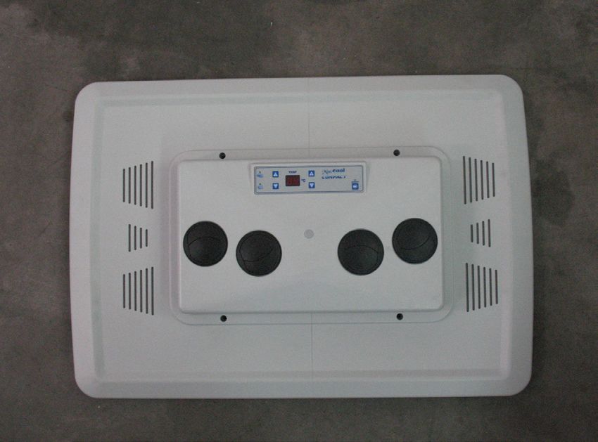
INTEGRAL POWER II                                         S
                                                          ES

     Desmontar tapa escotilla, los elementos de
 1   fijación y entregar éstos al cliente (*).

                                                      1

                                                      *

                                                      *

     Quitar los residuos sobrantes adheridas al
 2   techo antes de pegar la junta EPDM.

 2                                                    2

                                                  3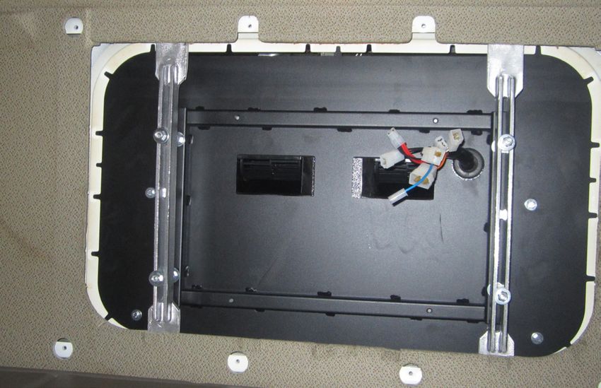
S
ES      INTEGRAL POWER II

         Pegue la junta EPDM alrededor del hueco
 3       de escotilla (mirar el detalle para cortar los
         bordes finales de unión de la junta).

                                                                  3

         COMO CORTAR LA JUNTA EPDM PARA                                                                       15 mm
 !       EVITAR FILTRACIÓN DE AGUA EN LA
                                                                      A
                       CABINA

         A- Pegar la junta, manteniendo 100 mm de
             papel protector por cada lado.

         B- Quita los dos piezas de papel.

         C- Pegue presionado ambos finales.

                                                                      Junta                                     Junta

                                                                                                            Techo cabina

                                                                          100 mm Aprox. (papel protector)

B                                                             C
Junta                                         Junta
                                                              Junta                                               Junta

                       Eliminar

                                                          4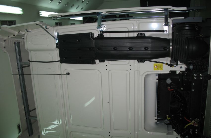
INTEGRAL POWER II                                                                                                 SS
                                                                                                                  E
                                                                                                                  ES

         EXTERIOR CABINA:
 4                                                                                                                4
         Posicionar el equipo Integral Power II en el
         hueco de la escotilla.

     4

         INTERIOR CABINA:
 5       Roscar 5 mm aproximadamente (4) espárragos
                                                                 5      Base                           5 mm
                                                                               Espárrago
         8/125x100-70 o 120 en las roscas de los
         refuerzos indicados (*), la medida se elegirá
                                                                                             Soporte
         tras presentar los soportes de sujección y
         teniendo en cuenta que los espárragos deben                                                   20 mm
         sobresalir de los mismos por la parte inferior
         unos 20 mm.

                                                                 *                                            *

         Colocar (1) arandela Ø 7 de goma, (1) arandela
 6       plana Ø 8 ala ancha, (2) tuerca M8 y (1) arandela   Arandela   Arandela plana                  Arandela plana
                                                              goma      Ø 8 ala ancha      Tuerca M8    Ø 8 ala ancha
         plana Ø 8 ala ancha , en cada uno de los
         espárragos anteriores; siguiendo dicho orden.

                                                             6

                                                        5
ES   INTEGRAL POWER II

         Colocar (2) soportes sujeción, con (4) arandela
 7       y (4) tuerca autoblocante M8, sin llegar a
                                                           7
         apretar.

     7

                                                                   7

         Roscar 10 mm (4) espárragos M6 x 55 o
 8       80, donde se indica, según distancia (D) del
                                                           8
         esquema del punto 11.

                                                               *                   *

         Colocar (1) arandela Ø6 de goma, (1) arandela
 9       plana Ø6 ala ancha y (1) tuerca M6, sobre
                                                                   9   Arandela
                                                                        goma
         cada uno de los espárragos de M6. Apretar
         tuerca, a continuación apretar tuerca hasta
         que la arandela de goma quede un poco                         Arandela
         oprimida.                                                     ala ancha

                                                                       Tuerca M6

                                                     6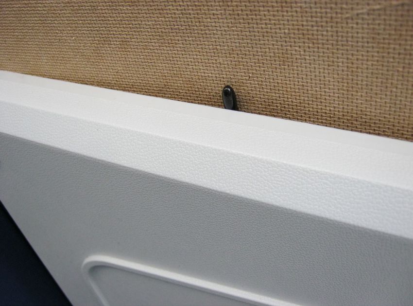
INTEGRAL POWER II                                                                                ES

         Conectar cableados del equipo con los del
10       panel interior de distribución de aire haciendo
         coincidir cajas y colores.

         Colocar panel interior de distribución de aire en
11       los espárragos anteriores con (1) arandela M6
                                                                 11
         ala ancha y (1) tuerca M6 en cada espárrago.
         Apretar tuercas hasta que los canalizadores
         hagan tope en goma espuma superior.

         Importante: Los canalizadores deben hacer
         tope contra la goma espuma superior para
         evitar fugas de aire.

11                       Base
     Junta                                                                          Gomaespuma
     EPDM

                                                D
                         Tuerca M6        (A)
 Techo cabina
                                                             Canalizadores
  Tapizado           Espárrago M6
                                                                             Panel interior
                       1 mm.                                                 de distribución
                                                                             de aire
                                Hexágonos M6

         Presentar consola y centrar el equipo. Una
12       vez centrado quitar consola.
                                                                 12

                                                       7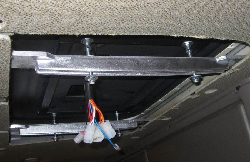
S
ES    INTEGRAL POWER II

           Fijar los soportes de sujección apretando las
 13        tuercas hasta el apriete de la junta de EPDM
                                                                           13
                                                                           12
           exterior (Punto 4) del equipo entre 3 y 6mm;
           la junta debe quedar con un espesor entre 19
           y 22 mm.
           Importante: Para evitar posibles filtraciones de
           agua al interior de la cabina se debe asegurar el                        Comprobar la
           apriete de la junta EPDM con la base del equipo                        compresión de la
                                                                                junta EPDM usando
           tal y como se indica en el esquema.                                  un flexómetro en las
                                                                                  cuatro esquinas.

                                     Junta EPDM

3-6mm.

Techo cabina

                                                             10 mm*
         Apretar las tuercas hasta
         el apriete de la junta de
13       goma entre 3 y 6 mm.                                                                  13
                                     (*) (aprox. después de apretar)

                                                             13

           Apretar (4) tuercas M8 al soporte y (4) a la
 14        base del equipo.
                                                                                               14

                                                                       8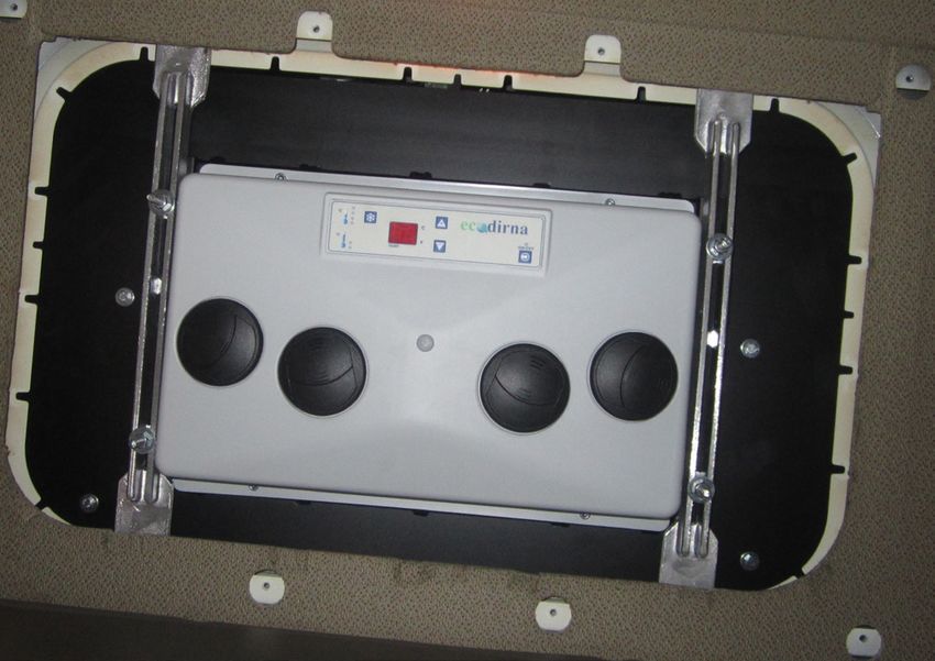
INTEGRAL POWER II                                                                                   S
                                                                                                    ES

         Conectar sensor aire de retorno a la clema
15       situada en el hueco de entrada de aire.
                                                          15

         Colocar tuerca M6 (A) tras la tuerca de           16
16       fijación del panel interior de distribución de                             Base
         aire en cada espárrago. Colocar hexágonos
         M6 roscándolo hasta que quede 1 mm por                          Exágono sujeción
                                                                   (A)
         encima del tapizado. Desenroscar tuercas M6
         (A) de este punto hasta que haga tope con los                                   Tapizado
         hexágonos y apretar contra estos.

                                                          1 mm
                                                          Aprox.

16                      Base
     Junta                                                               Gomaespuma
     EPDM

                        Tuerca M6        (A)
 Techo cabina

  Tapizado          Espárrago M6

                      1 mm.                                              Panel interior de
                                                                         distribución de aire
                               Exágonos M6

         Colocar la consola con (4) tornillos M6/100x15
17       allen.
                                                                                  17

                                                     9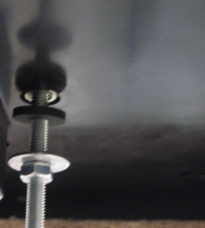
ES   INTEGRAL POWER II

          Atención: La sonda de recirculación deberá
18        quedar como se indica para que capte la
                                                              18
          temperatura del interior de la cabina.

     18

          Cubrir los (4) tornillos M6/100x15 allen con los
19        embellecedores redondos de plástico.
                                                             19

             19

                                                       10
INTEGRAL POWER II ES
TUBOS DE DESAGÜE
Montar (4) válvulas en tubos de desagüe.
1 1
1
Sujetar con (4) abrazaderas y (4) tornillos
2 como se indica.
2
2
Comprobar que no interfieren con el techo de
3 la cabina, para evitar que se obstruyan.
11ES INTEGRAL POWER II
Instrucciones detalladas sobre la instalación
del cableado de alimentación
Conectar el cable de alimentación superior en
4 la parte trasera del equipo y llevarlo por la parte
posterior de la cabina pegando los soportes de
plástico y fijándolo con bridas.
4
4
4
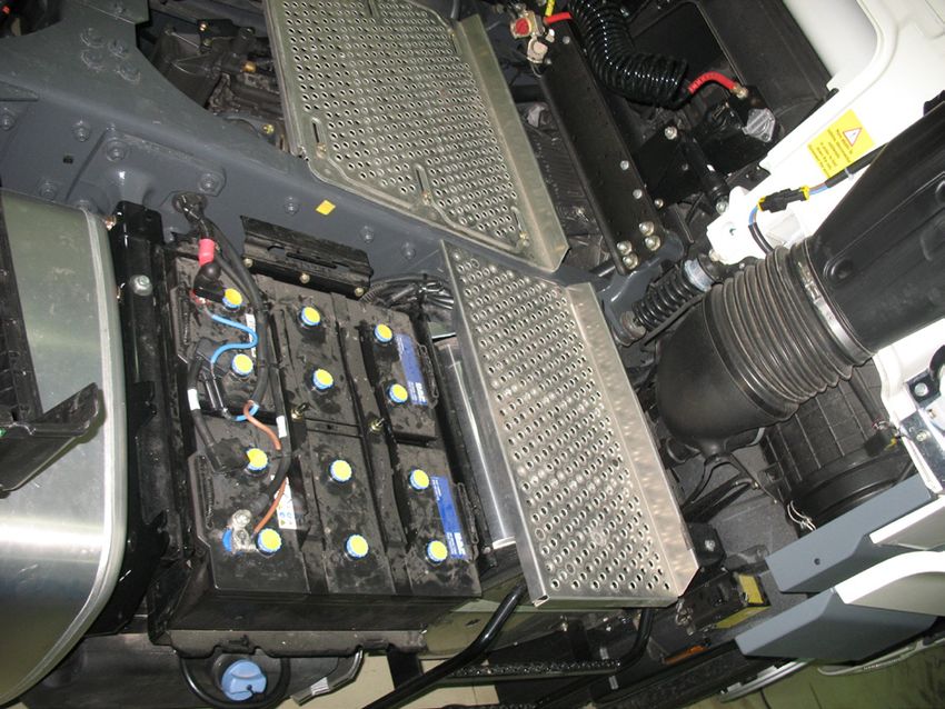
onectar cable de alimentación inferior en
C
5 batería, llevándolo por el paso de cableados
5
original, sujeto con bridas, hacia la parte
posterior de la cabina, para conectar con el
cable de alimentación superior.
5
12INTEGRAL POWER II ES
Cableado de
5
alimentación
superior
7
Importante: al conectar los cableados ,dejar la
! distancia adecuada ,para evitar su rotura por los
movimientos de la cabina.
Importante: Debido al complejo sistema de
6 regulación electrónica del equipo, la toma de
corriente debe realizarse directamente a la
batería del vehículo.
Importante: Para la puesta en marcha
consultar el Manual del Usuario.
6 6
+
-
13ES INTEGRAL POWER II
olocar adhesivos de peligro en unión de
C
7 cableado y en dispositivo de elevación de
7
cabina.
7
Cableado de conexión a alternador o bajo llave de contacto para
funcionamiento del equipo con motor en marcha
Atención: El cableado se instalará en todos
! los vehículos para que el equipo funcione a
8
motor arrancado.
Colocar cableado de excitación por el interior
8 o por el exterior del vehículo según convenga
y montar frente con tornillos roscachapa
suministrados. Conectar interruptores como
se indica.
Interruptor
por exterior
velocidades aire
Interruptor A/A
8 por interior
14INTEGRAL POWER II ES
Conectar el otro extremo del cableado
9 suministrado en posición (+) sólo con motor
arrancado o a través de (+) llave de contacto.
Conectar cable de alimentación superior en la
10 parte trasera del equipo.
10
15A
B
V
R
N
M
Az
Na
ES
Azul
Rojo
Verde
Negro
Blanco
Marrón
Naranja
Amarillo
Relé
Fusible 10 A
Control
(+) bajo llave o
electrónico
a motor de arranque
Sensor de
temperatura
Compresor Sensor
aire de retorno
Sensor
antihielo
INTEGRAL POWER II
Relé de
16
trabajo
Módulo compresor
Fusible
10 A
Fusible
Presostato 10 A
Fusible
Ventiladores del 10 A Soplador
condensador centrífugo
Centro de
conexiones
Fusible
80 A
Bateria
Esquema eléctricoINTEGRAL POWER II ES
17EN INTEGRAL POWER II
Assembly Tools
Recommendations Torx wrenches set
Allen wrenches set
• Before starting assembly, please read instructions and
Open-jawed spanner 13
follow them during installation process.
Scissors
•U
se the adequate tools for each operation. Flexo-meter
Electricity Related documentation
Mounting instructions 1002597509
• Disconnect ignition key.
User’s guide 1002192411
•D
isconnect battery before starting assembly. Troubleshooting 1002192414
•M
ake sure electric components are securely connected, Parts list 1002597510
checking their correct fitting.
Documentation included
Quick guide 1002455105
Warranty 220AA10017
! Warning Symbology
If the unit slants during assembly, wait for at least Fragile
60 minutes with the unit in horizontal position before
starting it up. Beware of cuts!
Electrical hazard
! Warnings
! Warning
! The
installing personnel must have a sufficient
training in vehicles air conditioning.
When installing air conditioning equipment on roof, the
upper cabin part must be protected with a cloth or a
! B
ergstrom shall not be responsible for breakdowns
protective blanket to avoid possible scratches. When or damages coming from an inadequate handling or
installing Integral Power II on roof, take into account that, installation of the equipment or from modifications
normally, cabins equipped with a hatch have a strong and substitutions carried out without our express
enough structure to hold equipment weight. However, and written authorisation.
if it is not the case and it is necessary to carry out a ! Equipment
pre-charged with refrigerating gas.
cut in the roof or, although it has a hatch, the material (Do not handle refrigerating gas circuit).
is not resistant enough (if roof is made of fibre, plastic, ! P
lease see product warranty procedure included
etc...), it is the installer who will have to decide, under in Troubleshooting.
his responsibility, if it is necessary to reinforce the roof to ! Please
see equipment User’s Guide for its correct
avoid possible deformations, breaks, water entries, etc., functioning of the remote control and control panel.
habilitating the means required to stop it from occurring.
! O
nce installation is finished, the following documents
With plastic roof cabins, take special care and must be handed over to the user: User’s Guide,
only rest on cabin nerves to avoid fibre part from Warranty and Troubleshooting.
sinking. ! A
ttention! Weight of the unit 52 kg.
18INTEGRAL POWER II EN
Take down the hatch cover and the
1 attachment elements, and hand them over to
the customer (*).
1
*
*
Remove any excess from the roof before
2 attaching the EPDM seal.
2 2
19EN INTEGRAL POWER II
Attach the EPDM seal around the hatch gap
3 (see the details to cut the ends of the seal
joint).
3
HOW TO CUT THE EPDM SEAL TO PREVENT 15 mm
! WATER FROM DRIPPING IN THE CABIN
A
A- Attach the seal, keeping 100 mm of
protection paper on each side.
B- Remove the two pieces of paper.
C- Attach by pressing both ends.
Seal Seal
Cabin roof
100 mm approx. (protection paper)
B C
Seal Seal
Seal Seal
Remove
20INTEGRAL POWER II EN
CABIN EXTERIOR:
4 4
Position the Integral Power II unit in the hatch
gap.
4
CABIN INTERIOR:
5 Thread about 5 mm (4) studs 8 / 125x100-70
5 Base 5 mm
Stud
or 120 on the threads of the reinforcements
indicated (*), the measurement will be chosen
Support piece
after aligning up the clamping brackets and
taking into account that the studs should 20 mm
protrude through the bottom by about 20 mm.
* *
Position (1) Ø7 rubber washer, (1) Ø8 flat wide- Ø8 Flat Ø8 Flat
6 rimmed washer, (2) M8 nut and (1) Ø8 flat wide- Rubber wide-rimmed wide-rimmed
washer washer M8 nut washer
rimmed washer on each of these studs, in the
same order.
6
21EN INTEGRAL POWER II
Position (2) fastening supports with (4) washer
7 and (4) M8 self-locking nut, without fully
7
tightening.
7
7
Thread 10 mm (4) M6 x 55 or 80 studs as
8 indicated, in accordance with the distance (D)
8
of the diagram in point 11.
* *
Position (1) Ø6 rubber washer, (1) Ø6 flat
9 wide-rimmed washer and (1) M6 nut on each
9 Rubber
washer
of the M6 studs. Tighten the nut until the
rubber washer compresses slightly.
Wide-rimmed
washer
M6 Nut
22INTEGRAL POWER II EN
Connect the equipment wiring with inner
10 air distribution panel making the boxes and
colours coincide.
Place the inner air distribution panel on the
11 previous studs with (1) wide brimmed M6
11
washer and (1) M6 nut on each stud. Tighten
nuts until channelling duct meets with the
upper foam of the equipment.
Important: The foam channelling duct must
meet the upper foam of the equipment to
prevent air leaks.
11 Base
EPDM Foam
seal
D
M6 Nut (A)
Cabin ceiling
Rubber ductings
Upholstering M6 stud
Interior air
1 mm. distribution
panel
M6 Hexagons
Position the console and align the unit. Once
12 aligned, remove the console.
12
23EN INTEGRAL POWER II
Secure the attachment supports by turning the
13 nuts to tighten the exterior EPDM seal (Point
13
12
4) of the unit between 3 mm and 6 mm; the
seal should have a thickness of between 19
and 22 mm.
Important: To prevent water infiltration into the
cabin ensure the tightness of the EPDM seal Check the
compression of the
with the base of the equipment as is shown in the EPDM seal using
a flexometer in the
diagram. four corners.
EPDM seal
3-6mm.
Cabin roof
10 mm*
Turn the nuts until the
rubber seal is tight
13 between 3 and 6 mm. 13
(*) (approx. after tightening)
13
Tighten (4) M8 nuts to the bracket and (4) to
14 the base of the equipment.
14
24INTEGRAL POWER II EN
Connect the return air sensor to the screw
15 terminals situated in the air inlet hole.
15
Place nut M6 (A) after the fixing nut of the 16
16 inner air distribution panel on each stud. Place Base
M6 hexagons screwing until 1 mm above the
upholstery. Unscrew nuts M6 (A) from this Front attachment hexagon
(A)
point until they meet the hex spacers and
tighten against them. Upholstery
1 mm
approx.
16 Base
EPDM Foam
seal
M6 nut (A)
Cabin roof
Upholstery M6 stud
1 mm. Interior air
distribution panel
M6 hexagons
Position the console with (4) M6/100x15 Allen
17 screws.
17
25EN INTEGRAL POWER II
Caution: The recirculation sensor must be as
18 indicated to capture the temperature inside
18
the cabin.
18
Cover the (4) M6 / 100x15 allen screws with
19 the round plastic trim.
19
19
26INTEGRAL POWER II EN
WASTEWATER PIPES
Mount (4) valves in wastewater pipes.
1 1
1
Secure with (4) clamps and (4) screws as
2 indicated.
2
2
Check that they do not interfere with the roof of
3 the cabin, thus ensuring no obstruction.
27EN INTEGRAL POWER II
Detailed instructions on the installation
of power supply cables
Connect the upper power cable in the rear of the
4 unit and run to the rear of the cabin, attaching
the plastic brackets and securing with flanges.
4
4
4
Connect the lower power cable to the battery by
5 running it through the original cabling passage,
5
secured with flanges, to the rear of the cabin
and connect to the upper power cable.
5
28INTEGRAL POWER II EN
Upper power
5
supply
cables
7
Important: When connecting the cables, leave
! suitable distance in order to prevent breakage
when the cabin moves.
Important: Due to the unit’s complex electronic
6 system, the power connection must be made
directly to the vehicle’s battery.
Important: Check the User Manual before
starting up.
6 6
+
-
29EN INTEGRAL POWER II
lace danger stickers at the cable joint and on
P
7 the cabin lifting device.
7
7
Connection to alternator cable for unit operation with
the engine running
Caution: The cable will be installed in all
! vehicles for the unit to work with the engine
8
started up.
Position excitation cable on the inside or
8 outside of the vehicle as appropriate, and
secure the front with the supplied self-tapping
screws. Connect switches as shown.
Air speed
switch on the outside
A/C switch
8 on the inside
30INTEGRAL POWER II EN
Connect the other end of the supplied cable in
9 position (+) only with the engine started up or
through the (+) ignition key.
Connect the upper power cable in the rear of
10 the unit.
10
31A
B
V
R
N
M
Az
Na
EN
Red
Blue
Black
White
Green
Brown
Yellow
Orange
Relay
Fuse 10 A
Electronic
(+) under key or
control
with starter motor
Temperature
sensor
Compressor Return
air sensor
Anti-freeze
sensor
INTEGRAL POWER II
Work
32
relay
Electronic module
of the compressor
Fuse
10 A
Fuse
Presostato 10 A
Fuse
Condenser 10 A Centrifugal
fans blower
Connections
center
Fuse
80 A
Battery
Electric wiringINTEGRAL POWER II EN
33FR INTEGRAL POWER II
Recommendations Outils
Pour Le Montage Jeu de clés Torx
Jeu de clés Allen
• Avant de commencer le montage de l’appareil, prière de Clé fixe 13
lire les instructions et de les suivre attentivement. Ciseaux
• Utiliser les outils convenant à chaque opération. Mètre
Electricity Documents rattachés
Instructions de montage 1002597509
• Déconnecter la clé de contact.
Guide de l’utilisateur 1002192411
•
Déconnecter la batterie avant de commencer le Solution des problèmes 1002192414
montage.
Liste de rechanges 1002597510
• Vérifier le câblage des composants électriques et leur
correcte installation. Documents joints
Guide rapide 1002455105
! Attention Garantie 220AA10017
Si pendant le montage l’équipement est incliné, Symbologie
il faudra attendre au moins 60 minutes avant de le
Fragile
mettre en marche une fois qu’il aura été remis sur sa
position horizontale.
Attention aux coupures !
! Attention Risque électrique
Lors de l’installation de l’appareil d’air conditionné sur le ! Garantie
toit, il faudra protéger la partie supérieure de la cabine
avec un linge ou une couverture de protection afin ! L’installateur
devra posséder la formation pertinente en
d’éviter les éventuelles égratignures. air conditionné sur véhicules.
Durant l’installation du Integral Power II, tenir compte ! Bergstrom
ne sera pas responsable des dommages
du fait que normalement les cabines pourvues d’écoutille ou des bris dérivés d’une installation ou d’une
possède une structure suffisamment solide pour supporter manipulation incorrecte ni des modifications réalisées
sans autorisation expresse par écrit.
le poids de l´appareil. Cependant, si ce n’est pas le cas
et qu’il est nécessaire de découper le toit ou même si ! A
ppareil pré-chargé de gaz réfrigérant. (Ne pas
disposant d’écoutille, la structure n’est pas suffisamment manipuler le circuit de gaz réfrigérant).
rigide (si elle était en fibre, plastique, etc.) il appartiendra ! Voir
la procédure de garantie du produit au Diagnostic
à l’installateur de décider s’il faut renforcer le toit pour de problèmes.
éviter toute déformation, rupture ou voie d’eau, etc., et ! V oir le Guide de l’Usager de l’appareil pour le
prendre les mesures nécessaires à cet effet. fonctionnement correcte de la télécommande et du
tableau de commande.
Prendre toutes les précautions requises pour les
cabines à toit haut en plastique et n’appuyer que sur
! A près l’installation, vous devez fournir à l’utilisateur:
Manuel d’utilisation, garantie et diagnostic de pannes.
les nerfs de la cabine afin d’éviter l’affaissement de
la pièce en fibre. ! Attention
! Le poids de l’équipement est de 52 Kg.
34INTEGRAL POWER II FR
Démonter le couvercle de l’écoutille, les
1 éléments de fixation et les remettre au client
(*).
1
*
*
Retirer les résidus adhérés au plafond avant
2 de coller le joint EPDM.
2 2
35FR INTEGRAL POWER II
Coller le joint EPDM autour du creux de
3 l’écoutille (observer le détail pour couper les
bords finaux d’union du joint).
3
COMMENT COUPER LE JOINT EPDM POUR 15 mm
! ÉVITER LA FILTRATION D’EAU DANS LA
A
CABINE
A- Coller le joint en maintenant 100 mm de
papier protecteur de chaque côté.
B- Retirer les deux pièces de papier.
C- Coller en exerçant une pression sur les
deux extrémités.
Joint Joint
Plafond cabine
100 mm approx. (papier protecteur)
B C
Joint Joint
Joint Joint
Éliminer
36INTEGRAL POWER II FR
EXTÉRIEUR CABINE:
4 4
Placer l’équipement Integral Power II dans le
creux de l’écoutille.
4
INTÉRIEUR CABINE :
5 Visser d’environ 5 mm (4) goujons 8/125x100-
5 Base 5 mm
Goujon
70 ou 120 dans les écrous des renforts
indiqués (*). La mesure sera choisie après
Support
avoir présenté les supports de fixation et
en tenant compte que les goujons doivent 20 mm
ressortir de ceux-ci d’environ 20 mm par la
partie inférieure.
* *
Placer (1) rondelle Ø 7 en caoutchouc, (1)
6 Rondelle plate Rondelle plate
rondelle plate Ø 8 surface large, (2) écrous M8 et Rondelle Ø 8 surface Ø 8 surface
caoutchouc large Écrou M8 large
(1) rondelle plate Ø 8 surface large dans chacun
des goujons précédents. Suivre l’ordre indiqué.
6
37FR INTEGRAL POWER II
Placer (2) supports de fixation avec (4)
7 rondelles et (4) écrous autobloquants M8,
7
sans serrer.
7
7
Visser 10 mm (4) goujons M6 x 55 ou 80, à
8 l’endroit indiqué, selon la distance (D) du
8
schéma du point 11.
* *
Placer (1) rondelle Ø6 en caoutchouc, (1)
9 rondelle plate Ø6 surface large et (1) écrou
9 Rondelle
M6 sur chaque goujon de M6. Serrer l’écrou caoutchouc
jusqu’à ce que la rondelle en caoutchouc reste
légèrement opprimée. Rondelle
surface large
Écrou M6
38INTEGRAL POWER II FR
Connecter les câblages de l’équipement à
10 ceux du panneau intérieur de distribution
d’air en faisant coïncider les boîtiers et les
couleurs.
Placer le panneau intérieur de distribution d’air
11 dans les goujons précédents avec (1) rondelle
11
M6 surface large et (1) écrou M6 sur chaque
goujon. Serrer les écrous jusqu’à ce que les
canalisateurs heurtent le caoutchouc mousse
supérieur.
Important: Les canalisateurs doivent heurter
le caoutchouc mousse supérieur pour éviter
des fuites d´air.
11 Base
Joint Mousse
EPDM
D
Écrou M6 (A)
Plafond cabine
Canalisateur
Tapisserie Goujon M6
Panneau
intérieur de
1 mm. distribution
Hexagones M6 d‘air
Présenter la console et centrer l’équipement.
12 Ensuite, retirer la console.
12
39FR INTEGRAL POWER II
Fixer les supports de fixation en serrant les
13 écrous jusqu’au serrage du joint en EPDM
13
12
extérieur (Point 4) de l’équipement entre 3 et
6mm ; le joint doit présenter une épaisseur
comprise entre 19 et 22 mm.
Important: Pour éviter de possibles filtrations
Vérifier la
d´eau à l´intérieur de la cabine, il faut assurer le compression
du joint EPDM
serrage du joint EPDM à la base de l’équipement, en utilisant un
comme indique le schéma. flexomètre dans les
quatre angles.
Joint EPDM
3-6mm.
Plafond cabine
10 mm*
Serrer les écrous jusqu’au
serrage du joint en
13 caoutchouc entre 3 et 6 mm.
13
(*) (environ après le serrage)
13
Serrer (4) écrous M8 au support et (4) à la
14 base de l’équipement.
14
40INTEGRAL POWER II FR
Connecter le capteur d’air de retour à la borne
15 placée dans le creux de l’entrée d’air.
15
Placer un écrou M6 (A) après l’écrou de fixation 16
16 du panneau intérieur de distribution d’air dans Base
chaque goujon. Placer les hexagones M6 en
vissant jusqu’à ce qu’il reste 1 mm au-dessus Hexagone fixation partie
(A)
de la tapisserie. Dévisser les écrous M6 (A) frontale
de ce point jusqu’à atteindre les hexagones et Tapisserie
serrer contre eux.
1 mm
approx.
16 Base
Joint Mousse
EPDM
Ecrou M6 (A)
Plafond Cabine
Tapisserie Goujon M6
1 mm. Panneau intérieur de
distribution d‘air
Hexagones M6
Placer la console avec (4) vis M6/100x15
17 allen.
17
41FR INTEGRAL POWER II
Attention : la sonde de recirculation devra
18 être placée tel que cela est indiqué pour
18
lui permettre de capter la température de
l’intérieur de la cabine.
18
Couvrir les (4) vis M6/100x15 allen avec les
19 enjoliveurs ronds en plastique.
19
19
42INTEGRAL POWER II FR
TUYAUX D’ÉCOULEMENT
Monter (4) vannes dans les tuyaux
1 d’écoulement.
1
1
Fixer avec (4) anneaux de serrage et (4) vis, tel
2 que cela est indiqué.
2
2
Vérifier qu’ils n’interfèrent pas avec le plafond
3 de la cabine, pour éviter une obstruction.
43FR INTEGRAL POWER II
Instructions détaillées sur l’installation
du câblage d’alimentation
Connecter le câble d’alimentation supérieur à
4 la partie arrière de l’équipement et le porter par
la partie postérieure de la cabine en collant les
supports en plastique et en le fixant avec des
brides.
4
4
4
Connecter le câble d’alimentation inférieur à la
5 batterie, en le portant par le passage original
5
des câbles, fixé avec des brides, vers la partie
postérieure de la cabine, pour une connexion
avec le câble d’alimentation supérieur.
5
44INTEGRAL POWER II FR
Alimentation
5
supérieur
câblage
7
Important: Au moment de la connexion des
! câblages, prévoir une distance suffisante pour
éviter des cassures à cause des mouvements
de la cabine.
Important: en raison de la complexité
6 du système de réglage électronique de
l’équipement, la prise de courant doit être
directement effectuée à la batterie du véhicule.
Important: Pour la mise en marche, consultez
la notice.
6 6
+
-
45FR INTEGRAL POWER II
Placer les adhésifs de danger dans l’union de
7 câblage et dans le dispositif de levage de la
7
cabine.
7
Câblage de connexion à alternateur pour fonctionnement
équipement avec moteur en marche
Attention: le câblage sera installé dans tous
! les véhicules pour que l’équipement fonctionne
8
avec le moteur démarré.
Placer le câblage d’excitation à l’intérieur
8 ou à l’extérieur du véhicule et monter avec
les vis taraudeuses fournies. Connecter les
interrupteurs comme cela est indiqué.
Interrupteur
vitesses air à l’extérieur
Interrupteur A/A
8 à l’intérieur
46INTEGRAL POWER II FR
Connecter l’autre extrémité du câblage fourni
9 sur la position (+) uniquement avec le moteur
démarré ou à travers (+) clé de contact.
Connecter le câble d’alimentation supérieur à
10 la partie arrière de l’équipement.
10
47A
B
V
R
N
M
Az
Na
FR
Vert
Noir
Bleu
Blanc
Jaune
Rouge
Marron
Orange
Relai
Fusible 10 A
Contrôle
(+) sous clé ou
électronique
avec démarreur
Capteur de
température
Compresseur Sonde de
retour d’air
Capteur
antigel
INTEGRAL POWER II
Relais de
48
travail
Module électronique
du compresseur
Fusible
10 A
Fusible
Pressostat 10 A
Fusible
Ventilateur du 10 A Souffleur
condenseur centrifuge
Centre
connexions
Fusible
80 A
Batterie
Câblage electriqueINTEGRAL POWER II FR
49GE INTEGRAL POWER II
Empfehlungen Werkzeuge
Zur montage Torx-Schraubenschlüssel
Inbusschraubenschlüssel
• Vor und während der Montage bitte diese Anweisungen
13er Schraubenschlüssel
lesen und beachten.
Schere
• Benutzen Sie für jeden Arbeitsschritt die geeigneten
Metermaß
Werkzeuge.
Zugehörige Dokumentation
Elektrizität
Montageanweisungen 1002597509
• Zündschlüssel abziehen. Benutzerleitfaden 1002192411
• Vor Montagebeginn die Batterie abklemmen. Fehlerdiagnose 1002192414
Ersatzteilliste 1002597510
• Den ordnungsgemäßen Anschluss und die korrekte
Installation der Elektrokomponenten überprüfen. Enthaltene Dokumentation
Kurzführer 1002455105
! Achtung
Garantie 220AA10017
Sollte sich das Gerät während der Montage neigen,
Symbologie
muss man mindestens 60 Minuten warten, nachdem
es wieder in die horizontale Lage gebracht wurde, Fragile
um es wieder einzuschalten.
Attention aux coupures !
! Achtung
Risque électrique
Wird die Klimaanlage im Kabinendach installiert, muss
der obere Teil der Kabine mit einem Tuch oder einer ! Warnhinweise
Decke gegen eventuelle Kratzer geschützt werden.
Bei der Installation der Integral Power II auf dem
! D
er Installateur muss im Bereich Fahrzeug-Klimaanlagen
ausreichend geschult sein.
Kabinendach muss darauf geachtet werden, dass mit
Luken ausgestattete Kabinen über eine ausreichend
! B
ergstrom übernimmt keine Verantwortung für Schäden
oder Brüche aufgrund einer nicht ordnungsgemäßen
stabile Struktur verfügen, um das Gewicht des Geräts
Installation oder Bedienung des Geräts oder den Austausch
Stand zu halten. Sollte das Fahrzeug über keine Luke
von Teilen bzw. Umbauten, die ohne die erforderliche
verfügen und sollte es notwendig sein, das Kabinendach
schriftliche Genehmigung durchgeführt wurden.
aufzuschneiden, bzw. sollte die vorhandene Struktur
! Mit
Kältemittel vorgefülltes Gerät.
nicht ausreichend stabil sein (z.B. wenn sie aus Faser,
(Kältemittelkreislauf nicht manipulieren).
Kunststoff usw. hergestellt ist), obliegt es dem Installateur
! S iehe Garantieverfahren des Produkts in der
zu entscheiden, ob das Kabinendach zur Vermeidung von
Fehlerdiagnose.
Verformungen, Brüchen, undichten Stellen usw. verstärkt
! S iehe Benutzerleitfaden des Geräts für den
werden muss, und die hierfür notwendigen Mittel bereit
ordnungsgemäßen Betrieb der Fernbedienung und des
zu stellen. Bedienfelds.
Bei Kabinen mit hohem Kunststoffdach des ! D
ie folgenden Unterlagen müssen dem Benutzer nach der
entsprechenden Vorsichtsmaßnahmen treffen und Installation ausgehändigt werden: Benutzerleitfaden,
das Gerät nur auf den Rippen der Kabine lagern, um Garantie und Fehlerdiagnose.
das Einsacken des Faserteils zu vermeiden. ! A
chtung! Anlagengewicht 52 kg
50INTEGRAL POWER II GE
Lukendeckel und dessen
1 Befestigungselemente ausbauen und diese
dem Kunden aushändigen (*).
1
*
*
Vor dem Ankleben der EPDM-Dichtung an der
2 Decke klebende Reste entfernen.
2 2
51GE INTEGRAL POWER II
Die EPDM-Dichtung um die Lukenaussparung
3 herum kleben (siehe Detailzeichnung
für das Zurechtschneiden der äußeren
Verbindungsränder).
3
ZURECHTSCHNEIDEN DER 15 mm
! EPDM-DICHTUNG ZUR VERMEIDUNG
A
DES EINDRINGENS VON WASSER IN DIE
KABINE
A- Dichtung ankleben, dabei auf jeder Seite
100 mm Schutzpapier stehen lassen.
B- Die zwei Papierstücke entfernen.
C- Beide Enden durch Andrücken ankleben.
Dichtung Dichtung
Kabinendecke
ca. 100 mm (Schutzpapier)
B C
Dichtung Dichtung
Dichtung Dichtung
Entfernen
52INTEGRAL POWER II GE
AUSSENSEITE KABINE:
4 4
Integral Power II in der Lukenaussparung
positionieren.
4
KABINENINNENSEITE:
5 (4) Stiftschrauben 8/125x100-70 bzw.
5 Grundplatte 5 mm
Stiftschraube
120 ca. 5 mm tief in die Windungen der
angegebenen Verstärkungen (*) schrauben.
Halterung
Das Maß wird gewählt, nachdem die
Befestigungshalterungen aufgelegt worden 20 mm
sind und unter Berücksichtigung der Tatsache,
dass die Stiftschrauben aus diesen auf der
Unterseite etwa 20 mm herausstehen müssen.
* *
An jeder Stiftschraube (1)
6
Breitflansch- Breitflansch-
Gummiunterlegscheibe Ø 7, (1) Breitflansch- Gummiunter- Flachscheibe Flachscheibe
legscheibe Ø8 Mutter M8 Ø8
Flachscheibe Ø 8, (2) Muttern M8 und
(1) Breitflansch-Flachscheibe Ø 8 in der
angegebenen Reihenfolge anbringen.
6
53GE INTEGRAL POWER II
(2) Befestigungshalterungen mit (4)
7 Unterlegscheibe und (4) selbstsichernder
7
Mutter M8 anbringen, ohne diese
festzuziehen.
7
7
10 mm (4) Stiftschrauben M6 x 55 ó 80 an den
8 angegeben Stellen je nach Abstand (D) des
8
Schemas in Punkt 11 eindrehen.
* *
(1) Gummiunterlegscheibe Ø6, (1)
9 Breitflansch-Flachscheibe Ø6 und (1)
9
Gummiunterlegscheibe
Mutter M6 auf jede Stiftschraube M6 legen.
Mutter anziehen, danach Mutter anziehen,
bis die Gummiunterlegscheibe ein wenig Breitflansch-
zusammengedrückt wird. Unterlegscheibe
Mutter M6
54INTEGRAL POWER II GE
Kabel des Geräts an die der inneren
10 Luftverteilertafel anschließen, wobei Kästen
und Färben übereinstimmen müssen.
Innere Luftverteilertafel an den vorgenannten
11 Stiftschrauben mit jeweils (1) Breitflansch-
11
Unterlegscheibe M6 und (1) Mutter M6
anbringen. Muttern anziehen, bis die
Führungen an den oberen Schaumstoff
anstoßen.
Wichtiger Hinweis: Die Führungen müssen
gegen den oberen Schaumstoff anstoßen, um
das Entweichen von Luft zu verhindern.
11 Grundplatte
EPDM- Schaumgummi
Dichtung
D
Mutter M6 (A)
Kabinendecke
Kabelführung
Verkleidung Stiftschraube M6
Innere
1 mm. Luftverteilertafel
Sechskantschrauben M6
Konsole auflegen und das Gerät zentrieren.
12 Nach dem Zentrieren Konsole entfernen.
12
55GE INTEGRAL POWER II
Die Befestigungshalterungen durch Anziehen
13 der Muttern befestigen, bis der Anzug der
13
12
äußeren EPDM-Dichtung (Punkt 4) des Geräts
zwischen 3 und 6mm liegt; die Dichtung muss
noch 19 bis 22 mm dick sein.
Wichtiger Hinweis: Um evt. Eindringen von
Wasser in das Kabineninnere zu vermeiden, Die Komprimierung
der EPDM-Dichtung
muss sichergestellt sein, dass die EPDM- an allen vier Ecken
mit einem Bandmaß
Dichtung wie im Schema angegeben fest auf der prüfen.
Gerätegrundplatte aufliegt.
EPDM-Dichtung
3-6mm.
Kabinendecke
10 mm*
Muttern anziehen, bis die
Gummidichtung zwischen
3 und 6 mm
13
13 zusammengedrückt ist. (*) (ca. nach dem Anziehen)
13
(4) Muttern M8 an der Halterung und (4) an
14 der Gerätegrundplatte anziehen.
14
56INTEGRAL POWER II GE
Abluftsensor an der am Lufteinlass
15 angebrachten Klemme anschließen.
15
Eine Mutter M6 (A) hinter der Befestigungsmutter 16
16 der inneren Luftverteilertafel an allen Grundplatte
Stiftschrauben anbringen. Sechskant-
Verbindungsmuttern M6 eindrehen, bis sie 1 Hexagonalschraube
(A)
mm über dem Bezug herausstehen. Muttern Befestigung Frontteil
M6 (A) dieses Punkts herausschrauben, bis Verkleidung
sie an den Sechskant-Verbindungsmuttern
anstoßen, und gegen diese anziehen.
Ca. 1
mm
16 Grundplatte
EPDM- Schaumgummi
Dichtung
Mutter M6 (A)
Kabinendecke
Verkleidung Stiftschraube M6
1 mm. Innere
Luftverteilertafel
Sechskantschrauben M6
Konsole anhand von (4)
17 Innensechskantschrauben M6/100x15
17
anbringen.
57GE INTEGRAL POWER II
Achtung: Die Rückführsonde muss wie
18 angegeben angebracht sein, damit die
18
Kabineninnentemperatur gemessen wird.
18
Die (4) Innensechskantschrauben M6/100x15
19 mit den runden Kunststoff-Zierkappen
19
abdecken.
19
58INTEGRAL POWER II GE
ENTWÄSSERUNGSROHRE
(4) Ventile in die Entwässerungsrohre
1 einbauen.
1
1
Mit (4) Rohrschellen und (4) Schrauben wie
2 gezeigt befestigen.
2
2
Sicherstellen, dass sie am Kabinendach genug
3 Platz haben und nicht verstopfen können.
59GE INTEGRAL POWER II
Detaillierte Anleitung für die Installation der Netzkabel
Das obere Netzkabel an der Gerätehinterseite
4 anschließen und an der Kabinenrückseite
unter Ankleben der Kunststoffhalterungen und
Befestigung durch Kabelbinder entlang führen.
4
4
4
Das untere Netzkabel an der Batterie
5 anschließen, entlang der Original-Kabelführung
5
führen, mit Kabelbindern befestigen, zur
Kabinenhinterseite führen und dort an das obere
Netzkabel anschließen.
5
60INTEGRAL POWER II GE
5
Oberes
Netzkabel
7
Wichtiger hinweis: Beim anschliessen der
! kabel zum vermeiden von schäden durch die
kabinenbewegungen ausreichend spielraum
lassen.
Wichtiger hinweis: Aufgrund der
6 komplizierten elektronischen Steuerung des
Geräts muss die Stromversorgung direkt an
der Fahrzeugbatterie erfolgen.
Wichtiger hinweis: Für die Inbetriebnahme
sehen Sie bitte im Benutzerhandbuch nach.
6 6
+
-
61GE INTEGRAL POWER II
Gefahrenhinweise an Kabelverbindung und
7 Kabinenhebevorrichtung anbringen.
7
7
Alternatoranschlussverkabelung für den Betrieb des Geräts
bei laufendem Motor
Achtung: Die Kabel in allen Fahrzeugen
! installieren, damit das Gerät bei laufendem
8
Motor funktioniert.
Erregerkabel von innen oder außen her
8 verlegen und Front mit den mitgelieferten
Blechschrauben befestigen. Schalter wie
gezeigt anschließe n.
Schalter
uftgeschwindigkeiten von außen
A/C-Schalter
8 von innen
62INTEGRAL POWER II GE
Das andere Ende des mitgelieferten Kabels
9 in Position (+) nur bei laufendem Motor oder
über (+) Kontaktschlüssel anschließen.
Oberes Stromkabel an der Hinterseite des
10 Geräts anschließen.
10
63A
B
V
R
N
M
Az
Na
GE
Rot
Blau
Gelb
Grün
Braun
Weiss
Orange
Schwarz
Relais
Sicherung 10 A
(+) unter der Taste Elektroniksteuerung
oder mit Anlasser
Temperaturfühler
Verdichter
Abluftsensor
Frostschutzsensor
INTEGRAL POWER II
64
Arbeitsrelais
Elektronikmodul
Verdichter
Sicherung
10 A
Sicherung
Druckschalter 10 A
Sicherung
Kondensatorlüfter 10 A
Zentrum
Verbindungen
Sicherung Zentrifugalgebläse
80 A
Batterie
ElektrischeVerkabelungINTEGRAL POWER II GE
65IT INTEGRAL POWER II
Suggerimenti Attrezzi
per il montaggio Kit di chiavi Torx
Kit di chiavi Allen
• Prima di cominciare il montaggio, leggere attentamente Chiave fissa 13
le istruzioni e rispettarle nel corso dello stesso.
Forbici
• Usare gli attrezzi più adatti ad ogni operazione. Metro a nastro
Elettricitá Documenti correlati
Istruzioni di montaggio 1002597509
• Scollegare la chiave di contatto.
Guida dell’utente 1002192411
• Scollegare la batteria prima di cominciare il montaggio. Soluzione dei problemi 1002192414
• Assicurarsi di aver effettuato correttamente l’installazione Elenco ricambi 1002597510
e il collegamento dei componenti elettrici.
Documentazione allegata all’impianto
Guida veloce 1002455105
! Attenzione Garanzia 220AA10017
Se durante il montaggio si inclina l’impianto, prima Simbologia
di rimetterlo in funzione occorre attendere almeno
Fragile
60 minuti dal momento in cui è di nuovo in posizione
orizzontale.
Attenzione alle mani
Tensione elettrica pericolosa
! Attenzione
! Avvertenze
Quando si installa l’impianto di aria condizionata sul
tettuccio, bisogna proteggere la parte superiore della ! L ’installatore deve essere in possesso della
formazione necessaria in materia di aria condizionata
cabina con uno straccio o una coperta per evitare per veicoli.
eventuali graffi. Per l’installazione del Integral Power
! Bergstrom
declina ogni responsabilità per danni o
II, tenere presente che normalmente le cabine munite di rotture derivanti dall’errata installazione o dall’errato
oblò dispongono di una struttura abbastanza solida per uso dell’impianto o da sostituzioni o modifiche
effettuate senza la necessaria autorizzazione per
sostenere il peso dell’impianto. Tuttavia, se così non fosse
iscritto.
e se fosse necessario tagliare il tettuccio, o se in presenza
! Impianto precaricato con gas refrigerante R-134.
di oblò la struttura non fosse abbastanza rigida (se fosse
(Non manomettere il circuito di gas refrigerante).
di fibra, plastica, ecc.), è responsabilità dell’installatore
! V
edi la procedura di garanzia del prodotto in
decidere se occorre rinforzare il tettuccio per evitare
Diagnosi dei problemi.
qualsiasi deformazione, rottura o penetrazione d’acqua,
! V
edi la Guida dell’utente dell’impianto per il corretto
ecc., prendendo le misure necessarie per evitarlo.
funzionamento del telecomando e del pannello di
controllo.
Prendere le misure necessarie con le cabine dal ! I seguenti documenti devono essere consegnati
tettuccio in plastica e appoggiare solo sui costoloni all’utente una volta conclusa l’installazione: Guida
della cabina per evitare lo sfondamento del pezzo in dell’utente, Garanzia e Diagnosi dei problemi.
fibra. ! Attenzione: peso dell’impianto 52 Kg.
66INTEGRAL POWER II IT
Smontare il portello e gli elementi di fissaggio
1 e consegnarli al cliente (*).
1
*
*
Rimuovere i residui eventualmente rimasti
2 attaccati al tetto prima di incollare la guarnizione
EPDM.
2 2
67IT INTEGRAL POWER II
Incollare la guarnizione EPDM intorno al foro
3 dell’oblò (vedi particolare per tagliare i bordi).
3
COME TAGLIARE LA GUARNIZIONE EPDM 15 mm
! A PER EVITARE INFILTRAZIONI NELLA
A
CABINA
A- Incollare la guarnizione mantenendo una
protezione di carta di 100 mm su ogni lato.
B- Rimuovere i due pezzi di carta.
C- Incollare premendo su entrambe le
estremità.
Guarnizione Guarnizione
Tettuccio della
cabina
Circa 100 mm (carta protettiva)
B C
Guarnizione Guarnizione
Guarnizione Guarnizione
Rimuovere
68INTEGRAL POWER II IT
ESTERNO CABINA:
4 4
Inserire l’impianto Integral Power II nel vano
del tettuccio apribile.
4
INTERNO CABINA:
5 Avvitare di circa 5 mm (4) viti prigioniere
5 Base 5 mm
Vite prigioniera
8/125x100-70 o 120 nelle filettature dei
rinforzi indicati (*): la misura va selezionata
Supporto
una volta posizionati i supporti di fissaggio e
tenendo conto che le viti prigioniere devono 20 mm
sporgere di circa 20 mm dalla parte inferiore
degli stessi.
* *
Inserire, nell’ordine: (1) rondella Ø 7 di gomma,
6 (1) rondella piana Ø 8 a testa larga, (2) dadi M8 e Rondella
Rondella piana
Ø 8 a testa
Rondella piana
Ø 8 a testa
gomma larga Dado M8 larga
(1) rondella piana Ø 8 a testa larga, su ciascuna
vite prigioniera precedente.
6
69IT INTEGRAL POWER II
Posizionare (2) supporti di fissaggio, con (4)
7 rondelle e (4) dadi autobloccanti M8, senza
7
stringere.
7
7
Avvitare di 10 mm (4) viti prigioniere M6 x 55 o
8 80, nei punti indicati, a seconda della distanza
8
(D) dello schema del punto 11.
* *
Inserire (1) rondella Ø 6 di gomma, (1)
9 rondella piana Ø 6 a testa larga e (1) dado M6
9 Rondella
gomma
su ogni vite prigioniera M6. Stringere il dado
fino a schiacciare leggermente la rondella di
gomma. Rondella a
testa larga
Dado M6
70INTEGRAL POWER II IT
Collegare i cablaggi dell’impianto con quelli
10 del pannello interno di distribuzione dell’aria
facendo coincidere le scatole con i colori.
Montare il pannello interno di distribuzione
11 dell’aria sulle viti prigioniere anteriori con (1)
11
rondella M6 a testa larga e (1) dado M6 su
ogni vite prigioniera. Stringere i dadi finché
i canalizzatori non sono a battuta sulla
gommapiuma superiore.
Nota bene: i canalizzatori devono essere
a battuta contro la gommapiuma per evitare
perdite d’aria.
11 Base
Guarnizione Gommapiuma
EPDM
D
Dado M6 (A)
Tettuccio cabina
Tappezzeria Canalizzatori
Vite prigioniera M6
Pannello
1 mm. interno
distribuzione
Perni esagonali M6 aria
Sistemare provvisoriamente la console
12 e centrare l’impianto. Una volta centrato,
12
rimuovere la console.
71IT INTEGRAL POWER II
Fissare i supporti di fissaggio stringendo i
13 dadi fino a stringere la guarnizione di EPDM
13
12
esterna (punto 4) dell’impianto tra 3 e 6 mm;
la guarnizione deve avere uno spessore
compreso tra 19 e 22 mm.
Nota bene: per evitare eventuali infiltrazioni
Verificare la
d’acqua all’interno della cabina, si deve assicurare compressione della
il serraggio della guarnizione EPDM con la base guarnizione EPDM
usando un metro a
dell’impianto come indicato nello schema. nastro sui quattro
angoli.
Guarnizione EPDM
3-6mm.
Tettuccio cabina
10 mm*
Stringere i dadi fino ad
ottenere il serraggio della
13 guarnizione di gomma
tra 3 e 6 mm. 13
(*) (circa dopo il serraggio)
13
Stringere (4) dadi M8 sul supporto e (4) sulla
14 base dell’impianto.
14
72INTEGRAL POWER II IT
Collegare il sensore dell’aria di ritorno al
15 morsetto situato nel vano di entrata dell’aria.
15
Inserire il dado M6 (A) dopo il dado di 16
16 fissaggio del pannello interno di distribuzione Base
dell’aria su ogni vite prigioniera. Inserire i perni
esagonali M6 e avvitarli fino a lasciarli a 1 mm Perno esagonale fissaggio
(A)
al di sopra della tappezzeria. Svitare i dadi M6
(A) di questo punto fino a battuta con i perni Tappezzeria
esagonali e stringerli contro gli stessi.
1 mm
Aprox.
16 Base
Guarnizione Gommapiuma
EPDM
Vite prigioniera M6 (A)
Tettuccio cabina
Dado M6 M6 Asparagi
1 mm. Pannello interno
distribuzione aria
Perni esagonali M6
Fissare la console con (4) viti a brugola
17 M6/100x15.
17
73IT INTEGRAL POWER II
Attenzione: La sonda di ricircolo de essere
18 posizionata come indicato per poter acquisire
18
la temperatura all’interno della cabina.
18
Coprire (4) viti a brugola M6/100x15 con i
19 tappini decorativi M6 di plastica.
19
19
74INTEGRAL POWER II IT
TUBI DI SCARICO
Montare (4) valvole sui tubi di scarico.
1 1
1
Fissare con (4) fissacavi e (4) viti come indicato.
2 2
2
Verificare che non interferiscano con il tettuccio
3 della cabina, per evitarne l’intasamento.
75IT INTEGRAL POWER II
Istruzioni particolareggiate per l’installazione
del cablaggio di alimentazione
Collegare il cavo di alimentazione superiore sulla
4 parte posteriore dell’impianto e farlo passare
dalla parte posteriore della cabina incollando i
supporti di plastica e fissandolo con le fascette.
4
4
4
ollegare il cavo di alimentazione inferiore alla
C
5 batteria, conducendolo dal passaggio originale
5
dei cablaggi, fissato con le fascette, verso la
parte posteriore della cabina, per il collegamento
con il cavo di alimentazione superiore.
5
76INTEGRAL POWER II IT
Cablaggio 5
alimentazione
superiore
7
Nota bene: quando si collegano i cablaggi,
! lasciare la distanza necessaria per evitarne la
rottura per i movimenti della cabina.
Nota bene: Dato il complesso sistema di
6 regolazione elettronica dell’impianto, la
corrente deve essere presa direttamente dalla
batteria del veicolo.
Nota bene: Per l’avviamento, vedi il Manuale
dell’utente.
6 6
+
-
77IT INTEGRAL POWER II
osizionare gli adesivi indicanti pericolo sulla
P
7 connessione del cablaggio e sul dispositivo di
7
sollevamento della cabina.
7
Cablaggio di connessione all’alternatore o sotto la chiave di accensione per il
funzionamento dell’impianto con il motore in moto
Attenzione: In tutti i veicoli il cablaggio si
! installa per fare funzionare l’impianto con il
8
motore in moto.
Inserire il cablaggio d’innesco dall’interno o
8 dall’esterno del veicolo a seconda di quanto
sia più comodo e montare il frontalino con
le viti per lamiera in dotazione. Collegare gli
interruttori come indicato.
Interruttore
dall’esterno
velocità aria
Interruttore A/C
8 dall’interno
78INTEGRAL POWER II IT
Collegare l’altra estremità del cablaggio in
9 dotazione in posizione (+) solo con il motore
in moto o tramite (+) la chiave di accensione.
Collegare il cavo di alimentazione superiore
10 alla parte posteriore dell’impianto.
10
79A
B
V
R
N
M
Az
Na
IT
Blu
Nero
Giallo
Verde
Rosso
Bianco
Marrone
Arancione
Relè
Fusibile 10 A
Controllo
(+) sotto chiave o con
elettronico
motorino d’avviamento
Sensore di
temperatura
Compressore Sensore
aria di ritorno
Sensore
antigelo
INTEGRAL POWER II
Relè di
80
lavoro
Modulo elettronico
compressore
Fusibile
10 A
Fusibile
Presostato 10 A
Fusibile
Ventilatore del 10 A Ventilatore
condensatore centrifugo
Centro
connessioni
Fusibile
80 A
Batteria
Cablaggio elettricoINTEGRAL POWER II IT
81Ed: 23/01/2020
Md:
Francisco Alonso, 6
28806 Alcalá de Henares, Madrid
SPAIN
Contact Phone Fax E-Mail
Sales
+34 91 8770510 +34 91 8771158 sales@dirna.bergstrominc.com
(Ventas Internacional)
Comercial Nacional +34 91 8775841 +34 91 8836321 ventas@dirna.bergstrominc.com
Orders & Deliveries
+34 91 8775846 +34 91 8771158 export@dirna.bergstrominc.com
(Logística internacional)
Orders & Deliveries
+34 91 8775840 +34 91 8836321 comercial@dirna.bergstrominc.com
(Logística nacional)
Technical Assistance
+49 511 86679681 +49 511 86679710 technicalassistance@dirna.bergstrominc.com
(Internacional)
Technical Assistance
+34 91 8775845 +34 91 883 6321 oblanco@dirna.bergstrominc.com
(Nacional)
www.dirna.com
Bergstrom se reserva el derecho de efectuar modificaciones en cualquier momento de los datos
! ATENCIÓN:
contenidos en esta publicación, por razones técnicas o comerciales.
For technical and commercial reasons, Bergstrom reserves the right to change the data contained in this
! NOTE:
brochure.
Bergstrom se réserve le droit d´effectuer à tout moment des modifications des données reprises sur cette
! ATTENTION:
publication, pour des raisons techniques ou commerciales.
Bergstrom behält sich vor, aus technischen oder kaufmännischen Gründen jederzeit Änderungen der
! HIWEIS:
Angaben dieser Veröffentlichung vorzunehmen.
Bergstrom si riserva il diritto di effettuare modifiche in qualsiasi momento ai dati contenuti in questa
! ATTENZIONE:
pubblicazione, per motivi tecnici o commerciali.También puede leer